IoT Multiband Antenna Solution
7-band, Single Antenna Solution for Cellular LTE NB IoT/CAT M1, Sub GHz, GPS/GNSS, & 2.4GHz
As the demand for a compact, all-encompassing solution for IoT connectivity continues to grow, we've developed a multi-band flexible solution using one antenna (p/n 0830AT54A2200). This antenna can resonate at multiple frequencies. For it to achieve high efficiency and bandwidth, it requires antenna matching networks to cover Cellular/SubGHz/GPS-GNSS/2.4GHz bands.
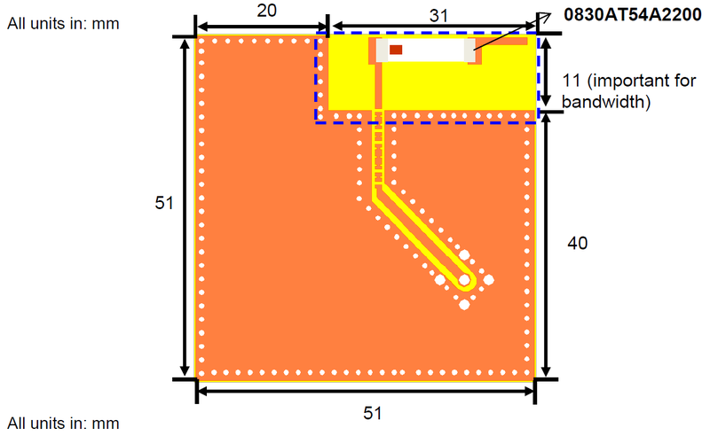
All characterizations and gains we measured on a small, 51x51mm PCB (including the antenna clearance).
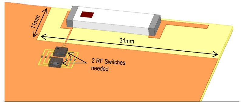
Below is a representation of the total antenna effective area and 2 switches required for this solution:
Introduction
In an effort to create a small-footprint antenna solution for cellular LTE, NB-IoT, geo location GPS/GNSS, and 2.4GHz frequency spectrums, Johanson has created a single antenna matching solution to cover all relative frequency bands. In addition to simplifying device bill-of-materials, costs can be reduced by re-using the same flexible solution in various applications.
By combining Johanson's 0830AT54A2200001E antenna with 2 channel switches, the designer has the ability to cycle through all usable channels mentioned above. Based on the number of channels required, we recommend the use of 2 (two), SP6T switches to cover the entire cellular spectrum as well as GPS/GLONASS and 2.4GHz Bluetooth or WiFi.
In our example, the Qorvo RFSW6062 switch is used. The Hexawave HWS556 is a substitute performance-wise, but it is not interchangeable.
Resource Links:
Antenna Datasheet 0830AT54A2200001E
Qorvo RFSW6062 Switch
Hexawave HWS556 Switch
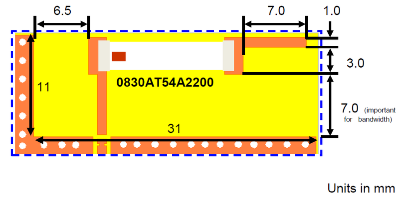
PCB size and Recommended Antenna Keep-out Area
Would you like the layout file for this?
Contact our RF Applications Engineers to review your layout at: Ask a question
Matching Network Topologies with Switches
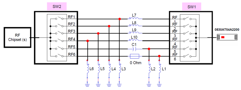
Frequency Channels and Matching Values
| Channel | Frequency (MHz) | L1 | L2 | L3 | L4 | L5 | L6 | L7 | L8 | L9 | L10 | C1 |
|---|---|---|---|---|---|---|---|---|---|---|---|---|
| 1 | 700 - 750 | 11nH | 30nH | |||||||||
| 2 | 750 - 800 | 10nH | 27nH | |||||||||
| 3 | 791 - 894 | 8.2nH | 22nH | |||||||||
| 4 | 880 - 960 | 6.9nH | 18nH | |||||||||
| 5 | 1574 - 1577* | 3.0nH | 0.9pF | |||||||||
| 6 | 1710 - 2200 2400 - 2480 | 24nH |
Channel 5 may be tuned for GLONASS operation (1598-1609MHz)
Would you like us to review your layout?
Contact our RF Applications Engineers to review your layout at: Ask a question
Measured Return Loss By Channel
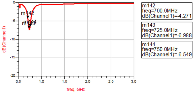
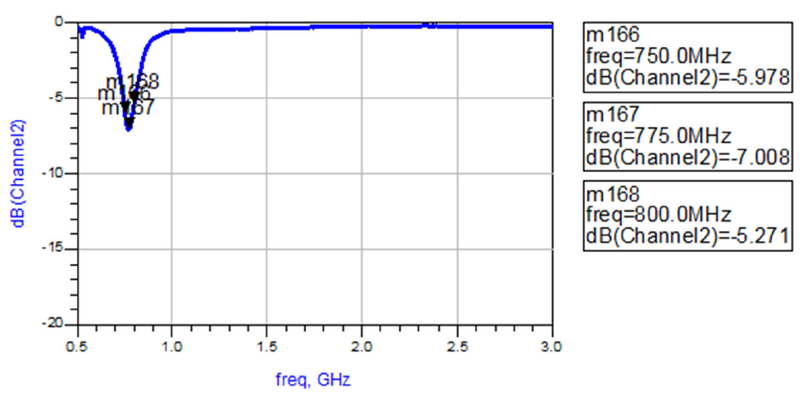
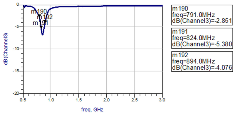
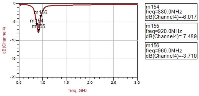
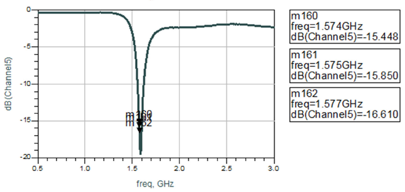
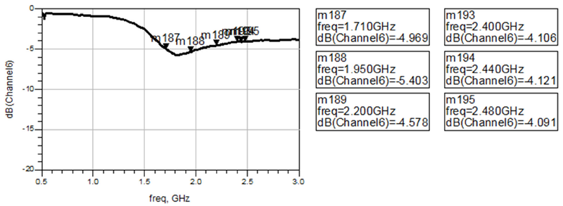
0830AT54A2200 Radiated Efficiency on 51x51mm board
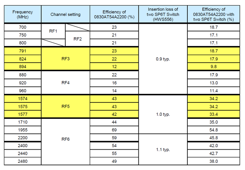
Performance based on example PCB with dimensions 51mm x 51mm