Antenna Bandwith Expansion Guide
Maximize Antenna Performance with Johanson’s Bandwidth Expansion Guide
Overview
This technical resource explains how to increase antenna bandwidth using proven layout techniques, matching networks, and ceramic RF components. Ideal for engineers working on Sub-GHz, 2.4GHz, and multi-band wireless designs in IoT, BLE, and LPWAN applications. Learn how to reduce return loss, optimize VSWR, and enhance overall RF efficiency—backed by real-world examples and layout tips.
Method for bandwidth expansion for chip antennas:
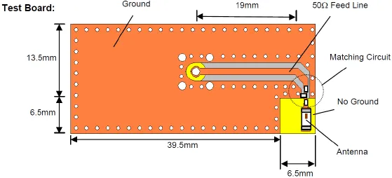
Layout with additional "elbow" to GND:
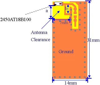
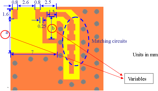
(B) Detailed land pattern with dimensions (+ 2 variables)
Return loss measurement (variables a and b dependent)
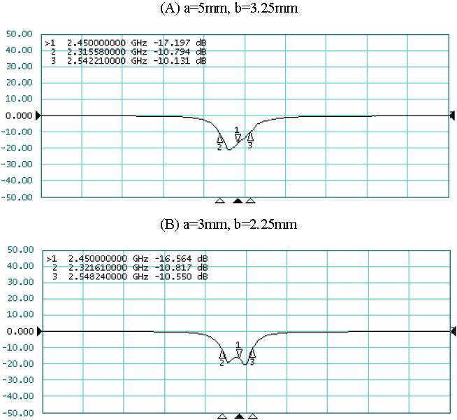
Bandwidth Summary with PIFA type. Table-1
| Case | New Bandwidth (S11) | Frequency Range |
|---|---|---|
| 1 = 5mm, b=3.25mm, h-direction_1 PIFA | 220 MHZ | 2.32 ~ 2.54GHZ |
| a=3mm, b=2.25mm h-direction_3 PIFA | 230MHz | 2.32 ~ 2.55GHz |