Single Layer, Microwave Capacitors (SLC)
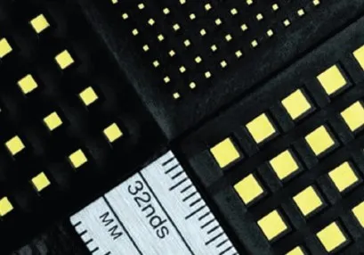
High-Frequency Capacitors for Microwave, Millimeter-Wave, and RF Applications
Overview:
Johanson Technology’s Microwave Single Layer Capacitors (SLCs) are designed for microwave and millimeter-wave RF designs requiring ultra-low loss, tight tolerances, and stable electrical performance at high frequencies. These capacitors support demanding applications in RF front-ends, microwave circuits, radar systems, and high-frequency communication infrastructure.
With ultra-low ESR and minimal parasitic inductance, SLCs enable reliable performance in RF bypass, DC blocking, impedance matching, and filter tuning circuits used in modern high-frequency systems.
Johanson Technology also provides custom Single Layer Capacitor solutions. Design engineers are encouraged to bring their specific electrical and mechanical requirements—our engineering team works directly with customers to develop components optimized for performance, reliability, and application-specific constraints.
Key Features:
- 100% Manufactured in USA for shorter lead times
- High self-resonant frequency (SRF) for microwave circuits
- Ultra-low ESR and ESL for minimal signal loss
- Tight capacitance tolerances for precision tuning
- Non-magnetic and RoHS compliant
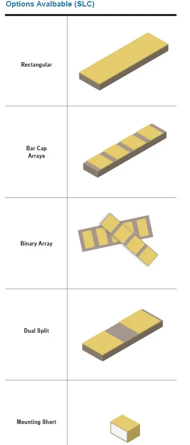
- Available in multiple case sizes and values
Typical Applications:
- RF tuning and filtering
- Impedance matching networks
- DC blocking and RF bypass in high-frequency designs
- Microwave and millimeter-wave circuits
- Radar and aerospace electronics
- Wireless infrastructure and medical RF systems
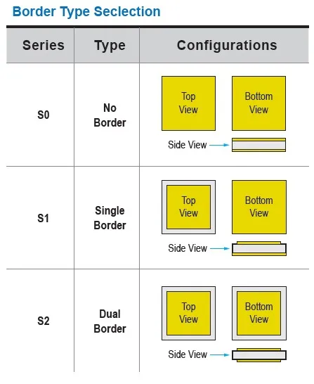
| Metalization Type | TiW/Au (Titanium-Tungsten/Gold) | TiW/Ni/Au (Titanium-Tungsten/Nickel/Gold) | TiW/Pt/Au (Titanium-Tungsten/Platinum/Gold) |
|---|---|---|---|
| Termination Code | S2 | S1 | S0 |
| Attachment Compatibility Wire / Ribbon Bonding | Wire / Ribbon Bonding Silver or Gold Conductive Epoxy Au/Ge or Au/Si Eutectic Preform Excellent High Temperature Resistance (400°C) Unsuitable for Pb/Sn or Au/Sn Soldering | Pb/Sn or Au/Sn Soldering Au/Sn Eutectic Preform Moderate High Temp. Resistance (325°C) Long term high temperature may cause Ni diffusion and wire bond problems on Au/Ge | Pb/Sn or Au/Sn Soldering Au/Sn Eutectic Preform Moderate High Temp. Resistance (325°C) Long term high temperature may cause Ni diffusion and wire bond problems on Au/Ge |
| Dielectric Code | Constant (K) | Temperature Coefficient | Temperature Range | Dissipation Factor (DF) | Test Conditions | Tolerances |
|---|---|---|---|---|---|---|
| G | 23 - 76 | 0 ± 30ppm | -55°C to +125°C | ≤ 0.15% @ 1MHz | 1 | B, C, D (A, <2pF) (F-K, >10pF) |
| D | 160 | -1,500 +500ppm / -946ppm | -55°C to +125°C | ≤ 0.25% @ 1MHz | 1 | J, K, M (B, C, D <10pF) |
| E | 440 | 2,200 +500ppm / -1,086ppm | -55°C to +125°C | ≤ 0.25% @ 1MHz | 1 | J, K, M (B, C, D <10pF) |
| P | 725 - 1,410 | ± 10% | -55°C to +125°C | ≤ 2.50% @ 1kHz | 2 | J, K, M (B, C, D <10pF) |
| W | 2,300 - 4,100 | ± 15% | -55°C to +125°C | ≤ 2.50% @ 1kHz | 2 | J, K, M (B, C, D <10pF) |
| U | 8,500 | +22% - 56% | +10°C to +85°C | ≤ 4.00% @ 1kHz | 2 | M, X |
| Y | 15,000 | +22% - 82% | -30°C to +85°C | ≤ 4.00% @ 1kHz | 2 | M, X |
| A | 15,000 - 65,000 | ± 15% | -55°C to +125°C | ≤ 2.50% @ 1kHz | 2 | K, M, X |
| Voltage Rating | 16; 25; 50; & 100 WVDC |
| Dielectric Strength | 2.5 x WVDC min, 25°C, 50 mA max |
| Test Conditions | Class 1 1.0 ± 0.2 VRMS @ 1MHz, 25°C Class 2 For values ≤ 100pF: 1.0±0.2 VRMS @ 1MHz, 25°C; for ALL other Values: 1.0±0.2 VRMS @1KHz,25°C Class 3 1.0±0.2 VRMS @ 1KHz |
(W) = Width. (L) = Length. (T) = Thickness. (B) = Border.
| S0AA | S0AG | S0AL | S0AP | S0AU | S0BC | S0BG | S0BL | S0BQ | S0BR | S0BT | ||
| (W) | inch | 0.010" +0.001"/-0.003" | 0.012" +0.001"/-0.003" | 0.015" +0.001"/-0.003" | 0.020" +0.001"/-0.003" | 0.025" +0.001"/-0.003" | 0.030" +0.001"/-0.003" | 0.035" ±0.005" | 0.040" ±0.005" | 0.050" ±0.010" | 0.070" ±0.010" | 0.090" ±0.010" |
| (mm) | (0.254mm +0.025mm/-0.076mm) | (0.305mm +0.025mm/-0.076mm) | (0.381mm +0.025mm/-0.076mm) | (0.508mm +0.025mm/-0.076mm) | (0.635mm +0.025mm/-0.076mm) | (0.762mm +0.025mm/-0.076mm) | (0.889mm ±0.127mm) | (1.016mm ±0.127mm) | (1.270mm ±0.254mm) | (1.778mm ±0.254mm) | (2.286mm ±0.254mm) | |
| (L) | inch | 0.012" Max | 0.015" Max | 0.020" Max | 0.025" Max | 0.030" Max | 0.035" Max | 0.040" Max | 0.045" Max | 0.060" Max | 0.080" Max | 0.100" Max |
| (mm) | (0.305mm Max) | (0.381mm Max) | (0.508mm Max) | (0.635mm Max) | (0.762mm Max) | (0.889mm Max) | (1.016mm Max) | (1.143mm max) | (1.524mm Max) | (2.032mm Max) | (2.450mm Max) | |
| (T) | inch | 0.006" ±0.0025" | 0.006" ±0.0025" | 0.006" ±0.0025" | 0.006" ±0.0025" | 0.006" ±0.0025" | 0.006" ±0.0025" | 0.006" ±0.0025" | 0.006" ±0.0025" | 0.006" ±0.0025" | 0.006" ±0.0025" | 0.006" ±0.0025" |
| (mm) | (0.153mm ±0.064mm) | (0.153mm ±0.064mm) | (0.153mm ±0.064mm) | (0.153mm ±0.064mm) | (0.153mm ±0.064mm) | (0.153mm ±0.064mm) | (0.153mm ±0.064mm) | (0.153mm ±0.064mm) | (0.153mm ±0.064mm) | (0.153mm ±0.064mm) | (0.153mm ±0.064mm) | |
| (T) for A - Dielectric | inch | 0.007±0.002 | 0.007±0.002 | 0.007±0.002 | 0.007±0.002 | 0.007±0.002 | 0.007±0.002 | 0.007±0.002 | 0.007±0.002 | 0.007±0.002 | 0.007±0.002 | 0.007±0.002 |
| (mm) | (0.177mm ±0.051mm) | (0.177mm ±0.051mm) | (0.177mm ±0.051mm) | (0.177mm ±0.051mm) | (0.177mm ±0.051mm) | (0.177mm ±0.051mm) | (0.177mm ±0.051mm) | (0.177mm ±0.051mm) | (0.177mm ±0.051mm) | (0.177mm ±0.051mm) | (0.177mm ±0.051mm) | |
| S1AA/S2AA | S1AG/S2AG | S1AL/S2AL | S1AP/S2AP | S1AU/S2AU | S1BC/S2BC | S1BG/S2BG | S1BL/S2BL | S1BQ/S2BQ | S1BR/S2BR | S1BT/S2BT | ||
| (WxL) | inch | 0.010" ±0.001" | 0.012" ±0.001" | 0.015" ±0.001" | 0.020" ±0.001" | 0.025" ±0.001" | 0.030" ±0.001" | 0.035" ±0.001" | 0.040" ±0.001" | 0.050" ±0.05" | 0.070" ±0.05" | 0.090" ±0.05" |
| (mm) | (0.254mm ±0.025mm) | (0.305mm ±0.025mm) | (0.381mm ±0.025mm) | (0.508mm ±0.025mm) | (0.635mm ±0.025mm) | (0.762mm ±0.025mm) | (0.889mm ±0.025mm) | (1.016mm ±0.025mm) | (1.270mm ±0.127mm) | (1.778mm ±0.127mm) | (2.286mm ±0.127mm) | |
| (T) | inch | 0.006" ±0.0025" | 0.006" ±0.0025" | 0.006" ±0.0025" | 0.006" ±0.0025" | 0.006" ±0.0025" | 0.006" ±0.0025" | 0.006" ±0.0025" | 0.006" ±0.0025" | 0.006" ±0.0025" | 0.006" ±0.0025" | 0.006" ±0.0025" |
| (mm) | (0.153mm ±0.064mm) | (0.153mm ±0.064mm) | (0.153mm ±0.064mm) | (0.153mm ±0.064mm) | (0.153mm ±0.064mm) | (0.153mm ±0.064mm) | (0.153mm ±0.064mm) | (0.153mm ±0.064mm) | (0.153mm ±0.064mm) | (0.153mm ±0.064mm) | (0.153mm ±0.064mm) | |
| (T) for A - Dielectric | inch | 0.007±0.002 | 0.007±0.002 | 0.007±0.002 | 0.007±0.002 | 0.007±0.002 | 0.007±0.002 | 0.007±0.002 | 0.007±0.002 | 0.007±0.002 | 0.007±0.002 | 0.007±0.002 |
| (mm) | (0.177mm ±0.051mm) | (0.177mm ±0.051mm) | (0.177mm ±0.051mm) | (0.177mm ±0.051mm) | (0.177mm ±0.051mm) | (0.177mm ±0.051mm) | (0.177mm ±0.051mm) | (0.177mm ±0.051mm) | (0.177mm ±0.051mm) | (0.177mm ±0.051mm) | (0.177mm ±0.051mm) | |
| (B) | inch | 0.001" (0.0005" min.) | 0.001" (0.0005" min.) | 0.002" ±0.001" | 0.002" ±0.001" | 0.002" ±0.001" | 0.002" ±0.001" | 0.002" ±0.001" | 0.002" ±0.001" | 0.003" ±0.001" | 0.003" ±0.001" | 0.003" ±0.001" |
| (mm) | (0.025mm, 0.013mm min) | (0.025mm, 0.013mm min) | (0.051mm ±0.025mm) | (0.051mm ±0.025mm) | (0.051mm ±0.025mm) | (0.051mm ±0.025mm) | (0.051mm ±0.025mm) | (0.051mm ±0.025mm) | (0.076 ±0.025mm) | (0.076 ±0.025mm) | (0.076 ±0.025mm) | |
Download datasheet to view our capacitance selection in details
How to Order
Valid options are shown except for Capacitance
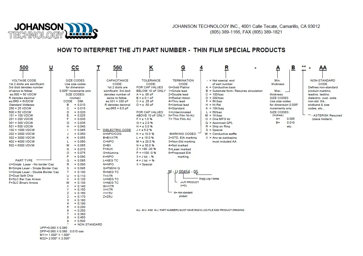
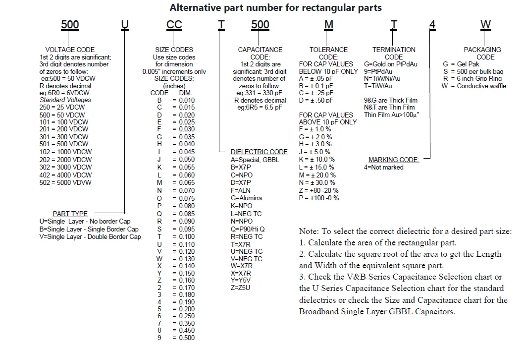
A typical PN is S0AA500G0R1A1ZZ001W. This part number breaks down as follows:
Capacitors Single Layer - No Bord, .010 x .010", NP0/C0G, 50V, 0.1pF±0.05pF, Special, Waffle Pack
New Johanson Global Part Number Breakdown
* Not all combinations create valid part numbers, ask our Apps Engineering Team for assistance creating a valid part number Request for assistanceClick below to see the new Global Part Number Reference Chart for this product
What is a Single Layer Capacitor (SLC)?
A Single Layer Capacitor (SLC) is a high-frequency ceramic capacitor constructed using a single dielectric layer rather than multiple stacked layers. This design delivers exceptionally high Q, low ESR, and excellent RF performance in microwave and high-frequency applications.
What are microwave single layer capacitors used for?
Microwave single layer capacitors are commonly used in:
- RF power amplifiers
- Microwave circuits
- Impedance matching networks
- RF filters
- Antenna matching
- Wireless infrastructure
- Test and measurement equipment
- Aerospace and defense systems
What are the advantages of single layer capacitors over MLCCs?
Single layer capacitors typically offer:
- Higher Q factor
- Lower ESR
- Better high-frequency performance
- Improved power handling
- Lower insertion loss
- Greater stability at microwave frequencies
What does High-Q mean in a microwave capacitor?
High-Q (Quality Factor) indicates that the capacitor stores energy efficiently with minimal losses. A higher Q factor helps improve circuit efficiency, reduce insertion loss, and maintain signal integrity in RF and microwave designs.
Why is low ESR important in RF applications?
Low ESR (Equivalent Series Resistance) minimizes energy loss and heat generation. This allows RF circuits to operate more efficiently while maintaining superior signal quality and power transfer.
Can microwave single layer capacitors handle high RF power?
Yes. Many microwave single layer capacitors are specifically designed for high-power RF circuits where low loss and thermal stability are critical.
Why choose Johanson Technology Microwave Single Layer Capacitors?
Johanson Technology Microwave Single Layer Capacitors provide:
- Ultra-high Q performance
- Low ESR and low insertion loss
- Excellent RF efficiency
- Reliable microwave frequency operation
- Strong power handling capability
- Proven performance in demanding RF and microwave applications