High Q Multilayer Ceramic Capacitors
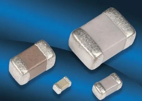
Low ESR, Low Loss Capacitors for High-Frequency, High-Power RF Applications
Overview:
Johanson Technology’s High-Q multilayer ceramic capacitors are engineered for high-frequency, high-power RF applications where low ESR, low loss, and thermal stability are critical. Designed and manufactured in North America, these capacitors deliver consistent performance across RF front-end designs, matching networks, and power amplifier stages.
Available globally, with fast sampling and expert support.
New Series!
P90 High-Q Capacitors for Low-Frequency Power Applications (<100MHz)
Key Features:
- Ultra-Low ESR for reduced signal loss and heat dissipation
- Low Loss NP0/COG Dielectric for maximum Q and tight tolerances
- Stable Self-Resonant Frequency (SRF) across wide bandwidths
- Non-Magnetic Options for sensitive RF environments
- RoHS Compliant for global environmental standards
- North American manufacturing for faster lead times and responsive support
- AEC-Q200 available upon request
Product Series Summary:
- L Series – High-Q capacitors for general RF and wireless applications
- C Series - Ultra-low loss, low loss High-Q Capacitors made with Copper electrodes
- S Series – Ultra high-Q capacitors for RF matching, VCOs, and filters
- G Series – Non-magnetic, High-Q Capacitors
- E Series – High voltage MLCCs for RF power and high voltage circuits
- P Series - Ultra stable, low ESR porcelain capacitors for low-frequency power applications (<100 MHz)
Typical RF Applications:
- Wireless infrastructure and telecom systems
- Aerospace and medical electronics
- Industrial RF and IoT applications
- High-density PCB layouts requiring precision tuning
Contact our RF Engineers about your design requirements.
All series are NP0/G0G used for high frequency applications
| Product Family Description | Product Family Series |
EIA Sizes | Capacitance Range | Electrode | Common Applications |
|---|---|---|---|---|---|
|
L Series | 0201 | 0.1 - 50pF | Silver/Palladium |
|
|
For Various RF & Wireless Applications
|
C Series | 0402 | 0.1 - 33 pF | Copper | |
| 0603 | 0.3 pF - 100 pF | Copper | |||
| 0805 | 0.3 pF - 220 pF | Copper | |||
|
For Various RF & Wireless Applications
|
S Series | 0402 | 0.1 - 33 pF | Silver/Palladium | |
| 0603 | 0.1 - 100 pF | Silver/Palladium | |||
| 0805 | 0.3 - 220 pF | Silver/Palladium | |||
|
For High-Power RF Applications
|
E Series | 1111 | 0.2 - 1000 pF | Silver/Palladium |
|
| 2525 | 1.0 - 2700 pF | Silver/Palladium | |||
| 3838 | 1.0 - 5100 pF | Silver/Palladium | |||
|
For MRI & Non-Magnetic Applications
|
G Series | 0805 | 0.3 - 47pF: 1000V | Silver/Palladium |
|
| 51pF - 100pF: 500V | |||||
|
For Low-Frequency High-Power RF (<100 MHz)
|
P Series | 0505 | 0.2pF-1000pF | P90 |
|
| 1111 | |||||
| 2525 | |||||
| 3838 | |||||
| 7676 |
| EIA Size/Cap. Value | Miniature Size - Portable Electronics | RF Power Applications | ||||||||||||||||
|---|---|---|---|---|---|---|---|---|---|---|---|---|---|---|---|---|---|---|
| 0201 (QL) | NEW | NEW | NEW | |||||||||||||||
| NPO (QLCD) | 0402 (QSCF) | 0402 (QCCF) | 0603 (QSCP) | 0603 (QCCP) | 0805 (QSCT) | 0805 (QLCT) | 0805 (QCCT) | 1111 (QEDB) | 2525 (QEEV) | 3838 (QEFM) |
||||||||
| pF | Code | Voltage | ||||||||||||||||
| 0.1 | 0R1 | A B C D |
25/50V | 50/250V | 250V | 250V | 500V | 1000V | ||||||||||
| 0.2 | 0R2 | 25/50V | 50/250V | 250V | 250V | 500V | 1000V | 500V | 1500V | |||||||||
| 0.3 | 0R3 | 25/50V | 50/250V | 250V | 250V | 500V | 250V | 1000V | 500V | 1500V | ||||||||
| 0.4 | 0R4 | 25/50V | 50/250V | 250V | 250V | 500V | 250V | 1000V | 500V | 1500V | ||||||||
| 0.5 | 0R5 | 25/50V | 50/250V | 250V | 250V | 500V | 250V | 1000V | 500V | 1500V | 3600V | |||||||
| 0.6 | 0R6 | 25/50V | 50/250V | 250V | 250V | 500V | 250V | 1000V | 500V | 1500V | 3600V | 3600V | 7200V | |||||
| 0.7 | 0R7 | 25/50V | 50/250V | 250V | 250V | 500V | 250V | 1000V | 500V | 1500V | 3600V | 3600V | 7200V | |||||
| 0.8 | 0R8 | 25/50V | 50/250V | 250V | 250V | 500V | 250V | 1000V | 500V | 1500V | 3600V | 3600V | 7200V | |||||
| 0.9 | 0R9 | 25/50V | 50/250V | 250V | 250V | 500V | 250V | 1000V | 500V | 1500V | 3600V | 3600V | 7200V | |||||
| 1.0 | 1R0 | 25/50V | 50/250V | 250V | 250V | 500V | 250V | 1000V | 500V | 1500V | 3600V | 3600V | 7200V | |||||
| 1.1 | 1R1 | 25/50V | 50/250V | 250V | 250V | 500V | 250V | 1000V | 500V | 1500V | 3600V | 3600V | 7200V | |||||
| 1.2 | 1R2 | 25/50V | 50/250V | 250V | 250V | 500V | 250V | 1000V | 500V | 1500V | 3600V | 3600V | 7200V | |||||
| 1.3 | 1R3 | 25/50V | 50/250V | 250V | 250V | 500V | 250V | 1000V | 500V | 1500V | 3600V | 3600V | 7200V | |||||
| 1.4 | 1R4 | 25/50V | 50/250V | 250V | 250V | 500V | 250V | 1000V | 500V | 1500V | 3600V | 3600V | 7200V | |||||
| 1.5 | 1R5 | 25/50V | 50/250V | 250V | 250V | 500V | 250V | 1000V | 500V | 1500V | 3600V | 3600V | 7200V | |||||
| 1.6 | 1R6 | 25/50V | 50/250V | 250V | 250V | 500V | 250V | 1000V | 500V | 1500V | 3600V | 3600V | 7200V | |||||
| 1.7 | 1R7 | 25/50V | 50/250V | 250V | 250V | 500V | 250V | 1000V | 500V | 1500V | 3600V | 3600V | 7200V | |||||
| 1.8 | 1R8 | 25/50V | 50/250V | 250V | 250V | 500V | 250V | 1000V | 500V | 1500V | 3600V | 3600V | 7200V | |||||
| 1.9 | 1R9 | 25/50V | 50/250V | 250V | 250V | 500V | 250V | 1000V | 500V | 1500V | 3600V | 3600V | 7200V | |||||
| 2.0 | 2R0 | 25/50V | 50/250V | 250V | 250V | 500V | 250V | 1000V | 500V | 1500V | 3600V | 3600V | 7200V | |||||
| 2.1 | 2R1 | 25/50V | 50/250V | 250V | 250V | 500V | 250V | 1000V | 500V | 1500V | 3600V | 3600V | 7200V | |||||
| 2.2 | 2R2 | 25/50V | 50/250V | 250V | 250V | 500V | 250V | 1000V | 500V | 1500V | 3600V | 3600V | 7200V | |||||
| 2.4 | 2R4 | 25/50V | 50/250V | 250V | 250V | 500V | 250V | 1000V | 500V | 1500V | 3600V | 3600V | 7200V | |||||
| 2.7 | 2R7 | 25/50V | 50/250V | 250V | 250V | 500V | 250V | 1000V | 500V | 1500V | 3600V | 3600V | 7200V | |||||
| 3.0 | 3R0 | 25/50V | 50/250V | 250V | 250V | 500V | 250V | 1000V | 500V | 1500V | 3600V | 3600V | 7200V | |||||
| 3.3 | 3R3 | 25/50V | 50/250V | 250V | 250V | 500V | 250V | 1000V | 500V | 1500V | 3600V | 3600V | 7200V | |||||
| 3.6 | 3R6 | 25/50V | 50/200V | 250V | 250V | 500V | 250V | 1000V | 500V | 1500V | 3600V | 3600V | 7200V | |||||
| 3.9 | 3R9 | 25/50V | 50/200V | 250V | 250V | 500V | 250V | 1000V | 500V | 1500V | 3600V | 3600V | 7200V | |||||
| 4.3 | 4R3 | 25/50V | 50/200V | 250V | 250V | 500V | 250V | 1000V | 500V | 1500V | 3600V | 3600V | 7200V | |||||
| 4.7 | 4R7 | 25/50V | 50/200V | 250V | 250V | 500V | 250V | 1000V | 500V | 1500V | 3600V | 3600V | 7200V | |||||
| 5.1 | 5R1 | B C D |
25/50V | 50/200V | 250V | 250V | 500V | 250V | 1000V | 500V | 1500V | 3600V | 3600V | 7200V | ||||
| 5.6 | 5R6 | 25/50V | 50/200V | 250V | 250V | 500V | 250V | 1000V | 500V | 1500V | 3600V | 3600V | 7200V | |||||
| 6.2 | 6R2 | 25/50V | 50/200V | 250V | 250V | 500V | 250V | 1000V | 500V | 1500V | 3600V | 3600V | 7200V | |||||
| 6.8 | 6R8 | 25/50V | 50/200V | 250V | 250V | 500V | 250V | 1000V | 500V | 1500V | 3600V | 3600V | 7200V | |||||
| 7.5 | 7R5 | 25/50V | 50/200V | 250V | 250V | 500V | 250V | 1000V | 500V | 1500V | 3600V | 3600V | 7200V | |||||
| 8.2 | 8R2 | 25/50V | 50/200V | 250V | 250V | 500V | 250V | 1000V | 500V | 1500V | 3600V | 3600V | 7200V | |||||
| 9.1 | 9R1 | 25/50V | 50/200V | 250V | 250V | 500V | 250V | 1000V | 500V | 1500V | 3600V | 3600V | 7200V | |||||
| 10 | 100 | F G J K |
25/50V | 50/200V | 250V | 250V | 500V | 250V | 1000V | 500V | 1500V | 3600V | 3600V | 7200V | ||||
| 11 | 110 | 25/50V | 50/200V | 250V | 250V | 500V | 250V | 1000V | 500V | 1500V | 3600V | 3600V | 7200V | |||||
| 12 | 120 | 25/50V | 50/200V | 250V | 250V | 500V | 250V | 1000V | 500V | 1500V | 3600V | 3600V | 7200V | |||||
| 13 | 130 | 25/50V | 50/200V | 250V | 250V | 500V | 250V | 1000V | 500V | 1500V | 3600V | 3600V | 7200V | |||||
| 15 | 150 | 25/50V | 50/200V | 250V | 250V | 500V | 250V | 1000V | 500V | 1500V | 3600V | 3600V | 7200V | |||||
| 16 | 160 | 25/50V | 50/200V | 250V | 250V | 500V | 250V | 1000V | 500V | 1500V | 3600V | 3600V | 7200V | |||||
| 18 | 180 | 25/50V | 50/200V | 250V | 250V | 500V | 250V | 1000V | 500V | 1500V | 3600V | 3600V | 7200V | |||||
| 20 | 200 | 25/50V | 50/200V | 250V | 250V | 500V | 250V | 1000V | 500V | 1500V | 3600V | 3600V | 7200V | |||||
| 22 | 220 | 25/50V | 50/200V | 250V | 250V | 500V | 250V | 1000V | 500V | 1500V | 3600V | 3600V | 7200V | |||||
| 24 | 240 | 25/50V | 50/200V | 250V | 250V | 500V | 250V | 1000V | 500V | 1500V | 3600V | 3600V | 7200V | |||||
| 27 | 270 | 25/50V | 50/200V | 250V | 250V | 500V | 250V | 1000V | 500V | 1500V | 3600V | 3600V | 7200V | |||||
| 30 | 300 | 25/50V | 50V | 250V | 250V | 500V | 250V | 1000V | 500V | 1500V | 3600V | 3600V | 7200V | |||||
| 33 | 330 | 25/50V | 50V | 250V | 250V | 500V | 250V | 1000V | 500V | 1500V | 3600V | 3600V | 7200V | |||||
| 36 | 360 | F G J K |
25/50V | 250V | 500V | 250V | 1000V | 500V | 1500V | 3600V | 3600V | 7200V | ||||||
| 39 | 390 | 25/50V | 250V | 500V | 250V | 1000V | 500V | 1500V | 3600V | 3600V | 7200V | |||||||
| 43 | 430 | 25/50V | 250V | 500V | 250V | 1000V | 500V | 1500V | 3600V | 3600V | 7200V | |||||||
| 47 | 470 | 25/50V | 250V | 500V | 250V | 1000V | 500V | 1500V | 3600V | 3600V | 7200V | |||||||
| 51 | 510 | 25/50V | 250V | 500V | 250V | 1000V | 500V | 1500V | 3600V | 3600V | 7200V | |||||||
| 56 | 560 | 250V | 500V | 250V | 1000V | 500V | 1500V | 3600V | 3600V | 7200V | ||||||||
| 62 | 620 | 250V | 500V | 250V | 1000V | 500V | 1500V | 3600V | 3600V | 7200V | ||||||||
| 68 | 680 | 250V | 500V | 250V | 1000V | 500V | 1500V | 3600V | 3600V | 7200V | ||||||||
| 75 | 750 | 250V | 500V | 250V | 1000V | 500V | 1500V | 3600V | 3600V | 7200V | ||||||||
| 82 | 820 | 250V | 500V | 250V | 1000V | 500V | 1500V | 3600V | 3600V | 7200V | ||||||||
| 91 | 910 | 250V | 500V | 250V | 1000V | 500V | 1500V | 3600V | 3600V | 7200V | ||||||||
| 100 | 101 | 250V | 500V | 250V | 1000V | 500V | 1500V | 3600V | 3600V | 7200V | ||||||||
| 110 | 111 | 250V | 500V | 300V | 1500V | 2500V | 3600V | 7200V | ||||||||||
| 120 | 121 | 250V | 500V | 300V | 1000V | 2500V | 3600V | 7200V | ||||||||||
| 130 | 131 | 250V | 500V | 300V | 1000V | 2500V | 3600V | 7200V | ||||||||||
| 150 | 151 | 250V | 500V | 300V | 1000V | 2500V | 3600V | 7200V | ||||||||||
| 160 | 161 | 250V | 500V | 300V | 1000V | 2500V | 3600V | 7200V | ||||||||||
| 180 | 181 | 250V | 500V | 300V | 1000V | 2500V | 3600V | 7200V | ||||||||||
| 200 | 201 | 250V | 500V | 300V | 1000V | 2500V | 3600V | |||||||||||
| 220 | 221 | 250V | 500V | 200V | 1000V | 2500V | 3600V | |||||||||||
| 240 | 241 | 200/500V | 200V | 600V | 2500V | 3600V | ||||||||||||
| 270 | 271 | 200/500V | 200V | 600V | 2500V | 3600V | ||||||||||||
| 300 | 301 | 200/500V | 200V | 600V | 1500V | 3600V | ||||||||||||
| 330 | 331 | 200/500V | 200V | 600V | 1500V | 3600V | ||||||||||||
| 360 | 361 | 200/500V | 200V | 600V | 1500V | 3600V | ||||||||||||
| 390 | 391 | 200/500V | 200V | 500V | 1500V | 3600V | ||||||||||||
| 430 | 431 | F G J K |
200/500V | 200V | 500V | 1500V | 2500V | |||||||||||
| 470 | 471 | 500V | 200V | 500V | 1500V | 2500V | ||||||||||||
| 510 | 511 | 100V | 200V | 500V | 1000V | 2500V | ||||||||||||
| 560 | 561 | 100V | 200V | 500V | 1000V | 2500V | ||||||||||||
| 620 | 621 | 100V | 200V | 500V | 1000V | 2500V | ||||||||||||
| 680 | 681 | 50V | 200V | 1000V | 2500V | |||||||||||||
| 750 | 751 | 50V | 200V | 1000V | 2500V | |||||||||||||
| 820 | 821 | 50V | 200V | 1000V | 2500V | |||||||||||||
| 910 | 911 | 50V | 200V | 1000V | 1000V | |||||||||||||
| 1000 | 102 | 50V | 200V | 1000V | 1000V | |||||||||||||
| 1200 | 122 | 50V | 1000V | 1000V | ||||||||||||||
| 1500 | 152 | 50V | 500V | 1000V | ||||||||||||||
| 1800 | 182 | 50V | 500V | 1000V | ||||||||||||||
| 2200 | 222 | 50V | 300V | 1000V | ||||||||||||||
| 2700 | 272 | 300V | 500V | |||||||||||||||
| 3300 | 332 | 500V | ||||||||||||||||
| 3900 | 392 | 500V | ||||||||||||||||
| 4700 | 472 | 500V | ||||||||||||||||
| 5100 | 512 | 500V | ||||||||||||||||
| 10000 | 103 | |||||||||||||||||
The Series Resonant Frequency is highly dependent on the substrate, pad dimensions, and measurement method. The below charts are for reference only.
EIA 0201 (QLCD Series) Resonant Frequency
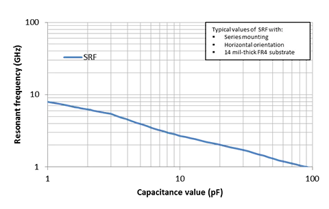
EIA 0402 (QSCF Series) Resonant Frequency
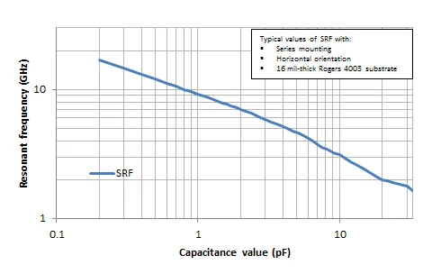
EIA 0603 (QSCP Series) Resonant Frequency
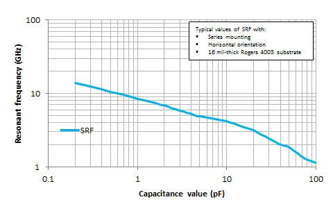
EIA 0805 (QSCT Series) Resonant Frequency
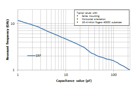
EIA 1111 (QEDB Series) Resonant Frequency
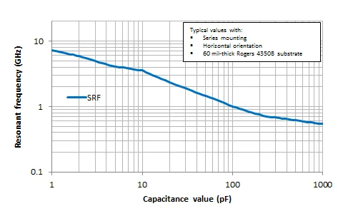
EIA 2525 (QEEV Series) Resonant Frequency
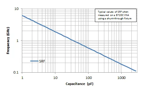
EIA 3838 (QEFM Series) Resonant Frequency
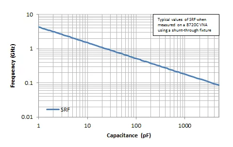
0201 (L Series) ESR
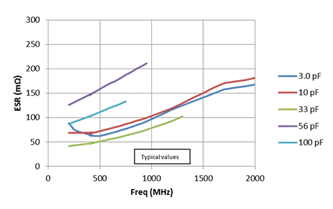
0402 (S Series) ESR
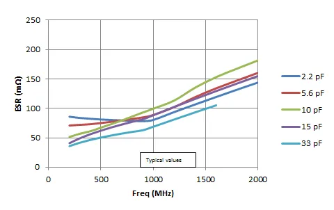
0603 (C Series) ESR
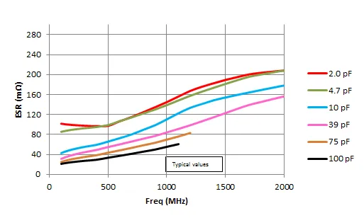
0805 (S Series) ESR
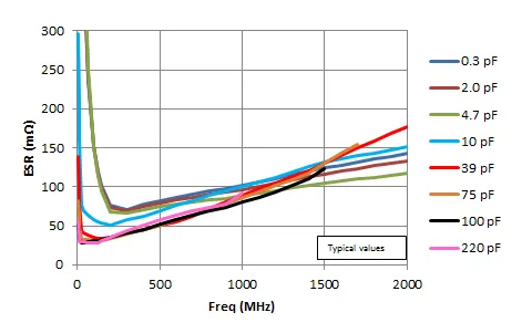
1111 (E Series) ESR
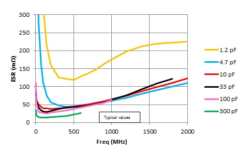
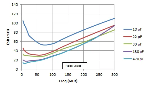
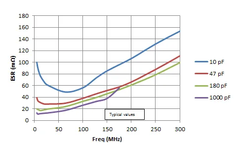
3838 (E Series) ESR
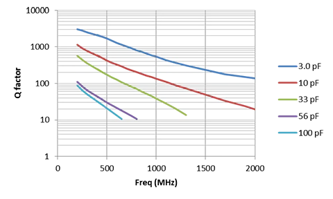
0201 (QLCD Series) Q Factor
0402 (QSCF Series) Q Factor
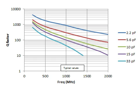
0603 (QSCP Series) Q Factor
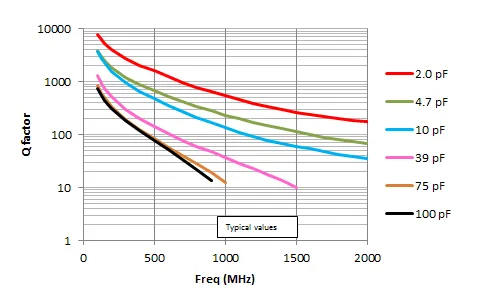
0805 (QSCT Series) Q Factor
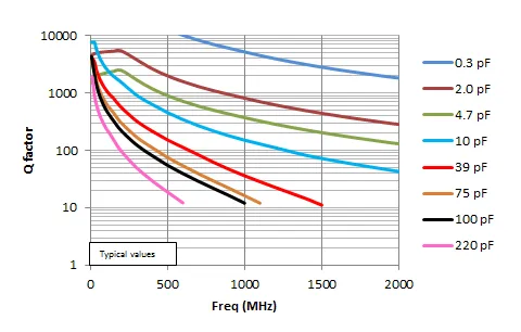
1111 (QEDB Series) Q Factor
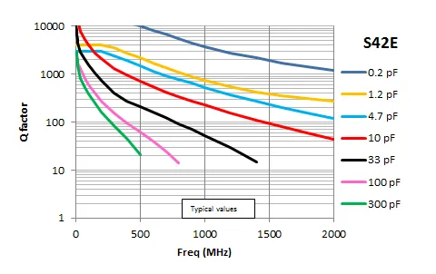
2525 (QEEV Series) Q Factor
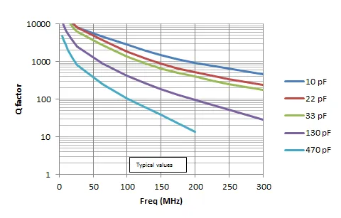
3838 (QEFV Series) Q Factor
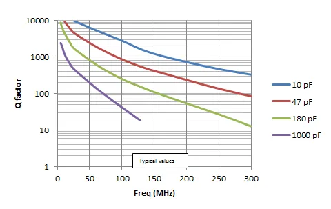
0201 (QLCD Series) Max RF Current
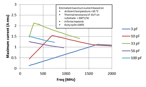
0402 (QSCF Series) Max RF Current
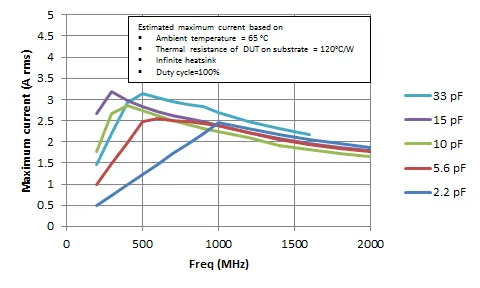
0603 (QSCP Series) Max RF Current
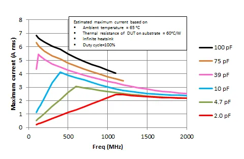
0805 (QSCT Series) Max RF Current
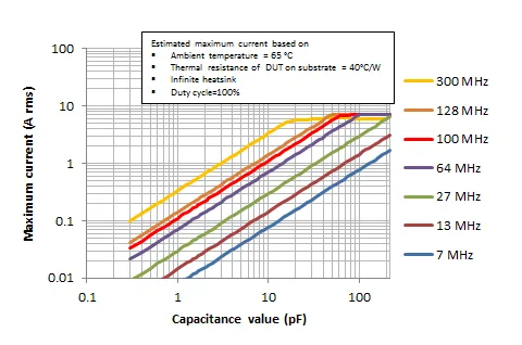
0805 (QSCT Series) Max RF Current
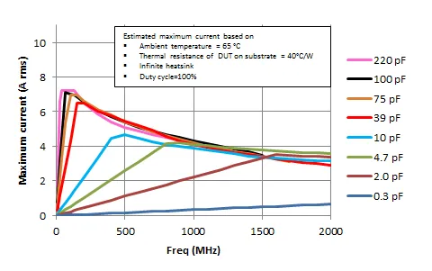
1111 (QEDB Series) Max RF Current
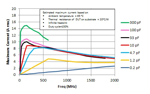
2525 (QEEV Series) Max RF Current
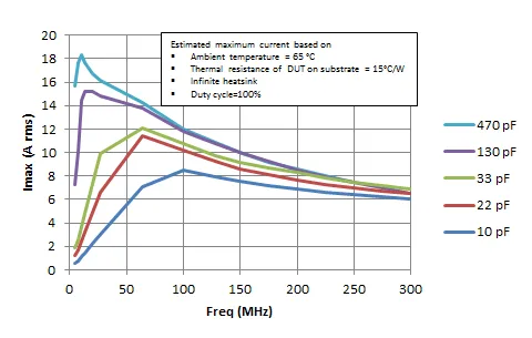
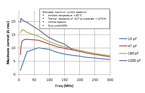
3838 (QEFM Series) Max RF Current
125°C IR is 10% of 25°C rating
1kHz ±50Hz, 1.0±0.2VRMS for capacitance values > 1,000pF
1000 V ≤ 1.5 X WVDC1 Min., 25°C, 50 mA max
> 1500 = 1.2 X WVDC1 Min., 25°C, 50 mA max
*On request, we can extend the highest temperature to +150°C for any of our High-Q Series
Mechanical Characteristics
| Size | Units | Length | Width | Thickness | End Band |
|---|---|---|---|---|---|
| EIA 0201 | In | .024 ± .001 | .012 ± .001 | .012 ± .001 | .008 Max. |
| Metric (0603) | mm | (0.60 ± 0.03) | (0.30 ± 0.03) | (0.30 ± 0.03) | (0.20 Max.) |
| EIA 0402 | In | .040 ± .004 | .020 ± .004 | .020 ± .004 | .010 ± .006 |
| Metric (1005) | mm | (1.02 ± 0.1) | (0.51 ± 0.1) | (0.51 ± 0.1) | (0.25 ± .15) |
| EIA 0603 | In | .062 ± .006 | .032 ± .006 | .030 + .005 /- .003 | .014 ± .006 |
| Metric (1608) | mm | (1.57 ± 0.15) | (0.81 ± 0.15) | (0.76 + .13 - .08) | (0.35 ± .15) |
| EIA 0805 | In | .080 ± .008 | .050 ± .008 | .040 ± .006 | .020 ± .010 |
| Metric (2012) | mm | (2.03 ± 0.20) | (1.27 ± 0.20) | (1.02 ± .15) | (0.50 ± .25) |
Environmental Characteristics
Automotive applications (AEC-Q200): Additional requirements. Consult factory for details.
| Specification | Test Parameters | |
|---|---|---|
| Solderability: | Solder coverage ≥ 90% of metalized areas No termination degradation | Preheat chip to 120°-150°C for 60 sec., dip terminals in rosin flux then dip in Sn62 solder @ 240°±5°C for 5±1 sec |
| Resistance to Soldering Heat : | No mechanical damage Capacitance change: ±2.5% or 0.25pFQ>500 I.R. >10 G OhmsBreakdown voltage: 2.5 x WVDC | Preheat device to 80°-100°C for 60 sec. followed by 150°-180°C for 60 sec. Dip in 260°±5°C solder for 10±1 sec. Measure after 24±2 hour cooling period |
| Terminal Adhesion: | Termination should not pull off. Ceramic should remain undamaged. | Linear pull force* exerted on axial leads soldered to each terminal. *0402 ≥ 2.0lbs, 0603 ≥ 4.0lbs (min.) |
| PCB Deflection: | No mechanical damage. Capacitance change: 2% or 0.5pF Max | Glass epoxy PCB: 0.5 mm deflection |
| Vibration: | No mechanical damage. Capacitance change: ±2.5% or 0.25pFQ>1000 I.R. ≥ 10 G-OhmBreakdown voltage: 2.5 x WVDC | Cycle performed for 2 hours in each of three perpendicular directions. Frequency range 10Hz to 55 Hz to 10 Hz traversed in 1 minute. Harmonic motion amplitude: 1.5mm. |
| Humidity, Steady State: | No mechanical damage. Capacitance change: ±5.0% or 0.50pF max. Q>300 I.R. ≥ 1 G-Ohm Breakdown voltage: 2.5 x WVDC | Relative humidity: 90-95% Temperature: 40°±2°CTest time: 500 +12/-0 HoursMeasure after 24±2 hour cooling period |
| Humidity, Low Voltage: | No mechanical damage. Capacitance change: ±5.0% or 0.50pF max.Q>300 I.R. = 1 G-Ohm min.Breakdown voltage: 2.5 x WVDC | Applied voltage: 1.5 VDC, 50 mA max. Relative humidity: 85±2%Temperature: 40°±2°CTest time: 240 +12/-0 HoursMeasure after 24±2 hour cooling period |
| Thermal Cycle: | No mechanical damage. Capacitance change: ±2.5% or 0.25pFQ>2000 I.R. >10 G OhmsBreakdown voltage: 2.5 x WVDC | 5 cycles of: 30±3 minutes @ -55°+0/-3°C, 2-3 min. @ 25°C, 30±3 min. @ +125°+3/-0°C,2-3 min. @ 25°CMeasure after 24±2 hour cooling period |
| Life Test: | MIL-STD-202, Method 1081 No mechanical damage. Capacitance change: ±3.0% or 0.3 pFQ>500 I.R. >1 G OhmsBreakdown voltage: 2.5 x WVDC | Applied voltage: 200% of WDVC for capacitors rated at 500 volts DC or less. Temperature: 125°±3°CTest time: 1000+48-0 hours |
Chip Capacitor Tape & Reel Packaging
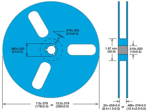
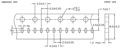
Johanson capacitors are available taped per EIA standard 481. Tape options include 5", 7" and 13" diameter reels. Johanson uses high quality, dust free, punched 8mm paper tape and plastic embossed 8mm tape for thicker MLCs. Quantity per reel ranges are listed in the tables below and are dependent on chip thickness.
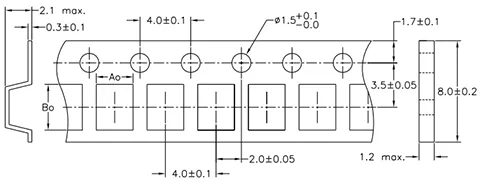
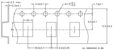
| TYPE / SIZE | 5” DIA. REEL SIZE | 7” DIA. REEL SIZE | 13” DIA. REEL SIZE | ||||||
|---|---|---|---|---|---|---|---|---|---|
| REEL QUANTITY | TAPE TYPE | TAPE CODE | REEL QUANTITY | TAPE TYPE | TAPE CODE | REEL QUANTITY | TAPE TYPE | TAPE CODE | |
| R05 / 0201 | 500 | Paper | Y | 15,000 | Paper | T | N/A | N/A | N/A |
| R07 / 0402 | 500 | Paper | Y | 10,000 | Paper | T | N/A | N/A | N/A |
| R14 / 0603 | 500 | Paper | Y | 4,000 | Paper | T | 10,000 | Paper | R |
| R15 / 0805 | 500 | Embossed | Z | 4,000 | Embossed | E | 10,000 | Embossed | U |
| S42 / 1111 | 500 | Embossed | Z | 2,000 | Embossed | E | 10,000 | Embossed | U |
| S48 / 2525 | N/A | — | — | 250 | Embossed | E | 1,000 | Embossed | U |
| S58 / 3838 | N/A | — | — | 250 | Embossed | E | 1,000 | Embossed | U |
| LASERtrim® (All) | 500 | Paper | Y | 4.5–5.0K | Paper | T | 15,000 | Paper | R |
SUBSTRATES – DEPENDS ON SIZE, TYPICAL IS 10/BOX CAP ARRAYS - 100/TRAY
SINGLE LAYER CAPACITORS - UP TO 50 MIL, 400/WAFFLE PACK; > 50 MIL, 100/WAFFLE PACK
SLC’S CAN ALSO BE MOUNTED ON GRIP RINGS, RING FRAMES, AND SURFTAPE
CUSTOM PACKAGING AND QUANTITIES ARE AVAILABLE, CONTACT THE FACTORY FOR OPTIONS
PLEASE VISIT OUR WEB SITE FOR RF CERAMIC COMPONENT PACKAGING INFORMATION.
Soldering Profiles and Guidelines for SMT Ceramic Components
General
Ceramic chip capacitors exhibit excellent reliability characteristics providing that proper circuit design techniques and controlled assembly processes are utilized. Due to the ceramic capacitor’s crystalline micro-structure these components are susceptible when exposed to excessive thermal or mechanical shock during circuit processing. It should be noted that micro-cracks in ceramic can be difficult to detect with normal post assembly visual and electrical testing and can pose a significant threat to reliable field operation. For this reason it is recommended that the assembly qualification process employ suitable testing to expose the presence of micro-cracking conditions.
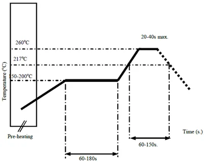
Figure 1: Solder Reflow Profile for Ceramic Capacitors and Inductors (JEDEC J-STD-020C compatible)
Ceramic components’ leads composition and soldering compatibility
High Frequency Ceramic Capacitors & Inductors - Offered with standard tin plated nickel-barrier terminations compatible with solder flow and reflow processes.
Single Layer Capacitors - Offered with Titanium-Tungsten/Gold and Titanium-Tungsten/ Nickel/Gold thin-film termination as well as legacy Platinum/Palladium/Gold terminations.
LASERtrim® Capacitors - Offered with gold flashed nickel-barrier terminations only. Due to the unique internal construction of the LASERtrim® it is recommended that a conservative reflow temperature profile be used (Fig. 5). Wave soldering is discouraged.
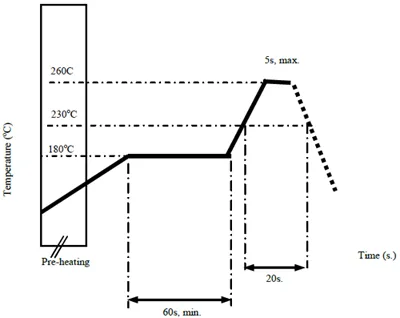
Figure 2: Solder Flow Profile for Ceramic Capacitors and Inductors.
Soldering Iron
Ceramic capacitor attachment with a soldering iron is discouraged due to the inherent limitations on precisely controlling soldering temperature, heat transfer rate, and time. In the event that a soldering iron must be employed the following precautions are recommended.
- Preheat circuit and ceramic component to 150°C
- ever contact the ceramic surface with the iron tip
- 30 watt iron output (max)
- 280°C tip temperature (max)
- 3.0 mm tip diameter (max)
- Limit soldering time to 5 sec.
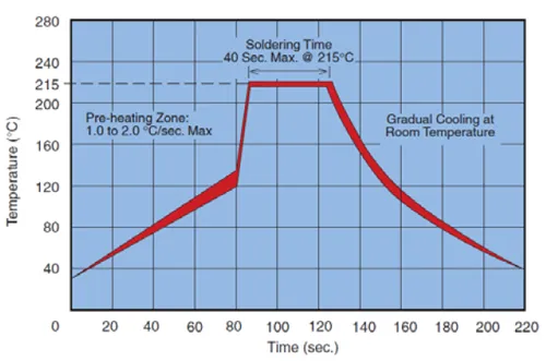
Figure 3: Vapor Phase Profile for MLCCs
Solder Pre-Heat Cycle
Proper preheating is essential to prevent thermal shock cracking of the capacitor. The circuit assembly should be preheated as shown in the recommended profiles at a rate of 1.0 to 2.0°C per second to within 65 to 100°C of the maximum soldering temperature.
- Preheat circuit and ceramic component to 150°C
- ever contact the ceramic surface with the iron tip
- 30 watt iron output (max)
- 280°C tip temperature (max)
- 3.0 mm tip diameter (max)
- Limit soldering time to 5 sec.
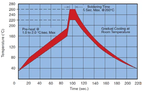
Figure 4: Wave Solder Profile for MLCCs
SMT Soldering Temperatures
Solders typically utilized in SMT have melting points between 179°C and 188°C. Activation of rosin fluxes occurs at about 200°C. Based on these facts a minimum peak reflow temperature of 205°C to 210°C should be established. A maximum peak reflow temperature of 225°C should be adequate in most circumstances. Many reflow process profiles have peaks ranging from 240°C to 260°C and while ceramic capacitors and inductors can withstand soldering temperatures in this range for short durations they should be minimized or avoided whenever possible. Use of PCB mounted multiple thermocouple M.O.L.E. profiling is advised for accurate characterization of circuit heat absorption and maximum temperature conditions.
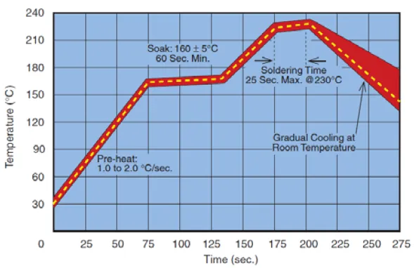
Figure 5: Solder Reflow Profile for LASERtrims®
Reflow Solder
The general term “reflow” refers to several methods used in heating the circuit so that solder paste reflows, or “wetting” of the ceramic capacitor and PCB contacts occurs. These methods include infrared, convection and radiant heating. The size of the solder fillet may be controlled by varying the amount of solder paste that is screened onto the circuit. Recommended temperature limits and times for solder reflow are shown in Figure 1 and 2 for Ceramic Capacitors and inductors and for LASERtrim® in Figure 5.
Vapor Phase
A typical vapor phase soldering process consists of several temperature zones created by saturated vapor from a boiling liquid. As the circuit passes through the zone the vapor condenses on the solder paste, pad, and termination resulting in heat transfer and reflow of the solder paste. Vapor phase reflow produces consistent circuit heating with reflow occurring at a relatively lower temperature that is determined by the known boiling point of the liquid used, typically 215°C. Recommended temperature limits for vapor phase reflow are shown in Figure 3.
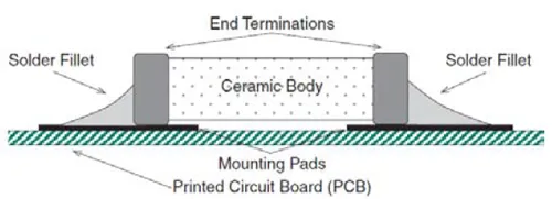
Figure 6
Solder Wave
Wave soldering is perhaps the most rigorous of surface mount soldering processes due to the steep rise in temperature seen by the circuit as it is immersed in the molten solder wave, typically at 240°C. Recommended temperature limits for wave soldering are shown in Fig. 4.
Cool Down Cycle
After the solder reflows properly the assembly should be allowed to cool gradually at room ambient conditions. Attempts to speed this cooling process or immediate exposure of the circuit to cold cleaning solutions may result in thermal shock cracking of the ceramic capacitor.
Solder Fillets
To avoid detrimental effects of thermal and mechanical stress it is essential that the solder fillet be limited to 2/3rds of the overall height of the MLC termination as illustrated in the figure below. The solder fillet can be controlled by solder paste deposition and pad design in reflow and vapor phase processes and by pad design and use of hot air knives in the wave process. As shown in Figure 6.
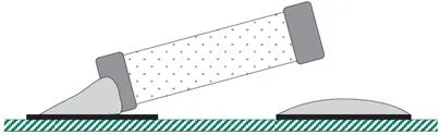
Tomb Stoning/Chip Movement
Tomb-stoning or draw bridging is illustrated in the figure below. Tomb-stoning or other undesirable chip movements may result if unequal surface tension forces exist as the molten solder wets the MLC terminations and mounting pads. This tendency can be minimized by insuring that all factors at both solder joints are equal, namely; pad size, solder mass, termination size, component position and heating. Tomb-stoning is easily avoided through proper design, material selection and proofing of the process. As shown in figure 7.
New Johanson Global Part Number Breakdown
Not all combinations create valid part numbers. Ask our Applications Engineering Team for assistance in creating a valid part number Request for assistance
Valid options are shown except for "Capacitance.
What is a High-Q RF Capacitor?
A High-Q RF capacitor is a multilayer ceramic capacitor (MLCC) specifically designed for RF and microwave circuits where low ESR, low loss, and high Q factor are critical. High-Q capacitors help maximize circuit efficiency and signal integrity in high-frequency applications.
What does "Q factor" mean in an RF capacitor?
Q factor, or Quality Factor, is a measure of a capacitor's efficiency. A higher Q indicates lower energy losses, making the capacitor better suited for RF matching networks, filters, oscillators, and resonant circuits.
What is ESR and why is low ESR important?
Equivalent Series Resistance (ESR) represents internal energy losses within a capacitor. Lower ESR results in reduced heating, improved efficiency, and better RF performance, particularly at high frequencies.
Why are High-Q capacitors important in RF designs?
High-Q capacitors minimize insertion loss, reduce power dissipation, and improve overall circuit performance. They are commonly used in RF front ends, wireless communications, and microwave applications where signal quality is critical.
What frequencies are High-Q capacitors designed for?
High-Q capacitors are optimized for high-frequency operation ranging from MHz frequencies into the GHz range, depending on the specific capacitor series and application requirements.
How do High-Q capacitors differ from standard MLCC capacitors?
While standard MLCCs are commonly used for general-purpose bypass and decoupling applications, High-Q RF capacitors are engineered for low loss, low ESR, stable RF performance, and high-frequency operation.
How do High-Q capacitors improve RF efficiency?
By reducing resistive losses and unwanted heating, High-Q capacitors improve power transfer and help maintain signal strength throughout the RF signal chain.
Are Johanson High-Q RF capacitors manufactured in North America?
Yes. Johanson Technology High-Q multilayer RF capacitors are designed and manufactured in North America, providing engineers with a domestic source for critical RF and microwave capacitors. This helps support supply chain stability, responsive technical support, and consistent product availability.
I'm looking for an alternative RF capacitor supplier. Why should I consider Johanson?
Engineers seeking an alternative source for High-Q RF capacitors often look for low ESR performance, consistent quality, reliable supply, and technical support. Johanson provides High-Q capacitor solutions manufactured in North America for RF matching, filtering, tuning, and power amplifier applications
Are Johanson High-Q capacitors suitable for aerospace, defense, and medical applications?
Johanson High-Q capacitors are suitable for demanding applications including aerospace, medical, telecommunications, industrial, and wireless infrastructure systems where stable RF performance and reliability are critical.