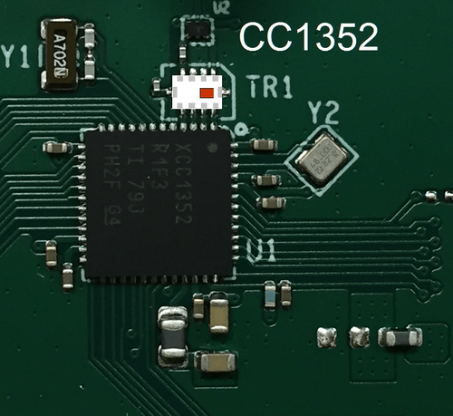
Texas Instruments CC1352 x Johanson Technology 0900PC15A0036

Introduction

Integrated passive components, known simply as IPCs, are devices designed with a complete circuit embedded into a single package rather than discretely placed on the PCB. With the advent of wearables and the overall miniaturization of electronic devices, it has become an ever-increasing priority among designers to reduce both size and complexity while maintaining comparable performance. In an effort to simplify the implementation of the TI CC1352R and CC1352P chipsets, Johanson Technology (JTI) and Texas Instruments (TI) have worked together to create a compact, matched solution for the TI CC1352R and CC1352P chipsets.


Introduction

The 0900PC15A0036 is an IPC designed by Johanson Technology to specifically operate in conjunction with TI chipsets CC1352R and CC1352P. Pairing the two devices together cuts down the number of components required for impedance matching, balun transformation, and harmonic filtering. For solutions with an integrated antenna, the RF passive component count is reduced from 23 to 3.

Figure 1 0900PC15A0036 RENDERING
FIGURE 1. 0900PC15A0036 RENDERING

COMPONENTS INTEGRATED

In order to illustrate the change in BOM that the 0900PC15A0036 provides, Figures 2 and 3 show the difference in component count between the IPC reference design and discrete reference design. This reduction also leads to decreased pick-and-place costs.


Figure 2 DISCRETE COMPONENTS INTEGRATED INTO IPC

FIGURE 2. DISCRETE COMPONENTS INTEGRATED INTO IPC


Figure 3 IPC REFERENCE DESIGN

FIGURE 3. IPC REFERENCE DESIGN

PCB SPACE REDUCTION

Figure 4 below is a to-scale comparison between the IPC reference design solution and the original discrete solution from Texas Instruments.

FIGURE 4. SIZE COMPARISON BETWEEN IPC AND DISCRETE COMPONENTS
FIGURE 4. SIZE COMPARISON BETWEEN DISCRETE COMPONENTS AND IPC

FIGURE 4. SIZE COMPARISON BETWEEN IPC AND DISCRETE COMPONENTS

Contact Johanson Technology below for complete component placement and layout guidelines.

PERFORMANCE COMPARISON

Table 1 below summarizes the overall link budget of JTI’s IPC vs. the discrete solution at maximum output power. In addition, Monte Carlo method shows that the IPC exhibits much more consistent performance over mass production when compared to the varying tolerances of 20+ individual L/C components.

TABLE 1. SUMMARY OF LINK BUDGET AT MAXIMUM POWER

Johanson Discrete
CC1352R IPC
Tx + Rx
868 MHz, 50 kbps
915 MHz, 50 kbps
2402-2480 MHz, 1 Mbps
121.6 123.0
122.1 123.0
100.3 101.8
CC1352P IPC
sep Tx Pa + Rx
868 MHz
915 MHz
2402-2480 MHz, 1 Mbps
129.2 129.0
128.8 129.0
115.9 116.5


A comprehensive look electrical and RF performance can be found in Texas Instruments’ application report SWRA629A.

CONTACT INFORMATION

Johanson Ask-a-question Johanson Technology hub for all support and technical inquiries
Texas Instruments E2E Texas Instruments’ engineer-to-engineer community