Capacitor Prototyping Kits
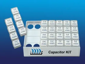
High-Q, Low ESR Capacitor Kits for RF and Microwave Design
Johanson Technology RF capacitor prototyping kits provide high-Q, low ESR capacitor selections for RF and microwave circuit design. These capacitor kits are used for matching networks, RF tuning, output networks, RF bypass, DC block, couplers, and detector applications across multiple package sizes and capacitance ranges.
High-Q, Low ESR Performance
Designed for RF and microwave applications where low loss, high efficiency, and stable performance are required.
Broad Capacitance and Package Coverage
Includes multiple capacitance values across common RF package sizes, enabling fast component selection during design and tuning.
RF Prototyping and Tuning Efficiency
Organized capacitor kits allow engineers to quickly test, compare, and optimize circuit performance without sourcing individual components.
Designed for RF Applications
Supports PA matching, output networks, RF bypass, DC block, couplers, detectors, and high-frequency circuit development.
Improved RF Performance
High-Q capacitors help improve return loss, VSWR, and overall RF system performance.
Non-Magnetic Capacitor Kit Option
Non-Magnetic RF Capacitor Kits for MRI, NMR, and other sensitive environments
Johanson reserves the right to make limited value/tolerance substitutions when necessary.
C- Series
Part Number: S402CHI
Contains 28 highest values in 0402 C-Series family:
B tolerance (± 0.10 pF) = 2.4, 2.7, 3.0, 3.3, 3.6, 3.9, 4.3, 4.7, 5.1, 5.6, 6.2, 6.8
C tolerance (± 0.25 pF) = 7.5, 8.2, 9.1
J tolerance (± 5%) = 10, 11, 12, 13, 15, 16, 18, 20, 22, 24, 27, 30, 33
Part Number: S402CLO
Contains 28 lowest values in 0402 C-Series family:
A tolerance (± 0.05 pF) = 0.1, 0.2, 0.3, 0.4, 0.5
B tolerance (± 0.10 pF) = 0.6, 0.7, 0.8, 0.9, 1.0, 1.1, 1.2, 1.3, 1.4, 1.5, 1.6, 1.7, 1.8, 1.9, 2.0, 2.1, 2.2, 2.4, 2.7, 3.0, 3.3, 3.6, 3.9
Part Number: S603CHI
Contains 28 highest values in 0603 C-Series family:
B tolerance (± 0.10 pF) = 4.7, 5.1, 5.6, 6.8
C tolerance (± 0.25 pF) = 7.5, 8.2, 9.1
J tolerance (±5%) = 10, 12, 15, 18, 20, 22, 24, 27, 30, 33, 36, 39, 43, 47, 51, 56, 68, 75, 82, 91, 100
Part Number: S603CLO
Contains 28 lowest values in 0603 C-Series family:
A tolerance (± 0.05 pF) = 0.2, 0.3, 0.4, 0.5
B tolerance (± 0.10 pF) = 0.6, 0.7, 0.8, 0.9, 1.0, 1.1, 1.2, 1.3, 1.4, 1.5, 1.6, 1.7, 1.8, 1.9, 2.0, 2.1, 2.2, 2.4, 2.7, 3.0, 3.3, 3.6, 3.9, 4.3
Part Number: S805CHI
Contains 28 highest values in 0805 C-Series family:
B tolerance (± 0.10 pF) = 5.6, 6.8,
C tolerance (± 0.25 pF) = 7.5, 8.2, 9.1
J tolerance (±5%) = 10, 12, 15, 18, 20, 22, 24, 27, 30, 33, 36, 39, 43, 47, 51, 56, 82, 100, 120, 150, 180, 220
Part Number: S805CLO
Contains 28 lowest values in 0805 C-Series family:
A tolerance (± 0.05 pF) = 0.3, 0.5
B tolerance (± 0.10 pF) = 0.6, 0.7, 0.8, 0.9, 1.0, 1.1, 1.2, 1.3, 1.4, 1.5, 1.6, 1.7, 1.8, 1.9, 2.0, 2.1, 2.2, 2.4, 2.7, 3.0, 3.3, 3.6, 3.9, 4.3, 4.7, 5.1
S-Series, and E-Series
Part Number: S402DS
Contains 50 PCS. EACH of the following 0402 capacitor sizes (pF):
B tolerance (± 0.10 pF) = 0.2, 0.3 , 0.5, 0.7, 0.9, 1.0, 1.2, 1.5, 1.8, 2.0, 2.2, 2.4, 2.7, 3.0, 3.6, 4.3, 4.7
C tolerance (± 0.25pF) = 5.6, 6.8, 7.5, 8.2, 9.1
J tolerance (±5%) = 10, 12, 15, 22, 27, 30
Part Number: S603DS
Contains 50 PCS. EACH of the following 0603 capacitor sizes (pF):
B tolerance (±0.10pF) = 0.3, 0.5, 0.8, 1.0, 1.2, 1.5, 1.8, 2.2, 2.7, 3.3, 3.6, 3.9, 4.7
C tolerance (±0.50 pF) = 5.6, 6.8, 8.2
J tolerance (±5%) = 10, 12, 15, 18, 20, 24, 27, 33, 39, 47, 68, 82
Part Number: S805DS
Contains 50 PCS. EACH of the following 0805 capacitor sizes (pF):
B tolerance (±0.10pF) = 4.7
C tolerance (±0.25pF) = 5.6, 6.8, 7.5, 8.2, 9.1
J tolerance (±5%) = 10, 12, 15, 18, 20, 22, 24, 27, 30, 33, 36, 39, 43, 47, 56, 68, 82
K tolerance (±10%) = 100, 120, 150, 180, 220
Contains 50 PCS. EACH of the following 0402 capacitor sizes (pF):
A tolerance (±0.05pF) = 0.2, 0.3, 0.4
B tolerance (±0.10pF) = 0.5, 0.6, 0.7, 0.8 0.9, 1.0, 1.1, 1.2, 1.3, 1.5, 1.8, 2.0, 2.2 2.4, 2.7, 3.0, 3.3, 3.6, 3.9, 4.3, 4.7
C tolerance (±0.25pF) = 5.1, 5.6, 6.2, 6.8
Part Number: S111DVE
Contains 10 PCS. EACH of the following 1111 capacitor sizes (pF):
B tolerance (±0.10pF) = 1.0, 3.9, 4.7
C tolerance (±0.25pF) = 6.8, 7.5, 8.2, 9.1
J tolerance (±5%) = 10, 12, 15, 18, 20, 27, 33, 47, 56, 68, 82, 100, 120, 150, 180, 220, 270, 390, 470
K tolerance (±10%) = 560, 1000
Tuning Kits
Contains 50 PCS. EACH of the following 0603 capacitor sizes (pF):
B tolerance (±0.10pF) = 0.2, 0.3, 0.4, 0.5, 0.6, 0.7, 0.8, 0.9, 1.0, 1.1, 1.2 , 1.3, 1.5, 1.8, 2.0, 2.2, 2.4, 2.7, 3.0, 3.3, 3.6
C tolerance (±0.25pF) = 3.9, 4.3, 4.7, 5.1 5.6, 6.2, 6.8
Contains 50 PCS. EACH of the following 0805 capacitor sizes (pF):
B tolerance (±0.10pF) = 0.3, 0.5, 0.7, 0.9, 1.0, 1.1, 1.2, 1.3, 1.5, 1.8, 2.0, 2.2, 2.4, 2.7, 3.0, 3.3, 3.6, 3.9, 4.3, 4.7
C tolerance (±0.25pF) = 5.1, 5.6, 6.2, 6.8, 7.5, 8.2, 9.1, 10
Contains 10 PCS. EACH of the following 1111 capacitor sizes (pF):
B tolerance (±0.10pF) = 0.5, 0.6, 0.7, 0.8, 0.9, 1.0, 1.0, 1.1, 1.2, 1.3, 1.5, 2.0, 2.2, 2.4, 2.7 3.0, 3.3, 3.6, 3.9, 4.3, 4.7
C tolerance (±0.25pF) = 5.1, 5.6, 6.2, 6.8, 7.5, 8.2, 9.1, 10
What Are High-Q Capacitors Used For in RF Designs?
High-Q capacitors are used in RF and microwave circuits where low loss and efficient signal transmission are critical. Common applications include impedance matching networks, antenna tuning, power amplifier matching, RF bypass, DC blocking, couplers, detectors, and high-frequency signal paths. High-Q capacitors help minimize energy loss and support improved RF performance
Why Are High-Q Capacitors Important for RF Matching Networks?
High-Q capacitors help reduce insertion loss and improve impedance matching in RF circuits. By minimizing energy dissipation, they can improve return loss, VSWR, power transfer efficiency, and overall RF system performance. High-Q capacitor selections are commonly used during RF tuning and matching network optimization
What Is ESR and Why Does Low ESR Matter in RF Circuits?
Equivalent Series Resistance (ESR) represents the resistive losses within a capacitor. Low ESR capacitors are preferred in RF and microwave applications because they reduce signal loss, improve efficiency, and help maintain consistent performance at high frequencies. Johanson's RF capacitor kits are designed for low ESR operation in demanding RF applications.
How Do RF Capacitor Prototyping Kits Accelerate Design Cycles?
RF capacitor prototyping kits provide engineers with a broad range of capacitance values and package sizes in a single kit. This allows rapid evaluation, tuning, and optimization of RF circuits without repeatedly ordering individual components, helping shorten development cycles and reduce design iterations
What Package Sizes Are Available in Johanson RF Capacitor Kits?
Johanson RF capacitor prototyping kits include a variety of common RF package sizes, including 0402, 0603, 0805, and 1111, allowing engineers to evaluate components that align with their design and layout requirements
What Capacitors Are Used for RF Bypass and DC Blocking Applications?
High-Q capacitors are commonly used for RF bypass and DC blocking functions in wireless and RF systems. These capacitors help isolate DC signals, support signal integrity, and improve RF circuit performance in transmit and receive paths
How Can High-Q Capacitors Improve RF Performance?
High-Q capacitors can help improve return loss, VSWR, efficiency, and signal integrity by minimizing losses within the RF signal path. These characteristics make them valuable for antenna matching, power amplifier circuits, filters, couplers, and other high-frequency RF application