Dual Prototyping Kits
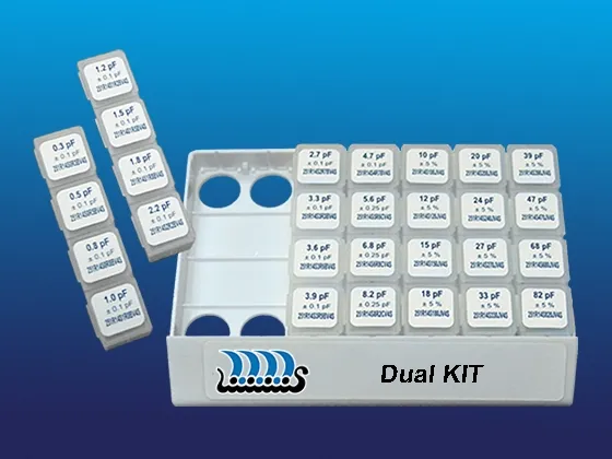
High-Performance Passive Components for Dual PA Matching Networks in IoT, BLE, and Wi-Fi Designs
Johanson Technology’s Dual RF Prototyping Kits offer a wide selection of high-frequency ceramic components specifically curated for RF engineers. These kits are ideal for prototyping dual matching networks in applications such as wireless modules, IoT devices, BLE, Zigbee, Wi-Fi, and more.
Each kit contains a carefully selected range of capacitors, inductors, and other RF components, along with the most recent product data from Johanson’s High Frequency Ceramic Solutions line. This ensures engineers have the tools they need to achieve high-performance RF design across multiple bands and technologies.
Typical Kit Contents
The Dual Prototyping Kits typically include:
- Components for dual PA matching networks
- Capacitors for DC blocking and RF bypass
- Inductors for impedance tuning
- Common values used in RF front-end circuits
These kits are ideal for rapid prototyping, evaluation, and tuning of dual RF paths, helping design engineers streamline development cycles.
Need Specific or Critical Values?
If your application requires specific capacitor or inductor values for tight-tolerance designs or uncommon frequencies, contact us.
Our engineers will support in selecting a kit that matches your critical RF specs.
Johanson reserves the right to make limited value/tolerance substitutions when necessary.
Part Number: L/C-402DS
50 PCS EACH (pF):
0.2 B, 0.3 B, 0.5 B, 0.7 B, 0.9 B, 1.0 B, 1.2 B, 1.5 B, 1.8 B, 2.0 B, 2.2 B, 2.4 B, 2.7 B, 3.0 B, 3.6 B, 4.3 B, 4.7 B, 5.6 C, 6.8 C, 7.5 C, 8.2 C, 9.1 C, 10 J, 12 J, 15 J, 22 J, 27 J, 30 J
50 PCS. EACH (nH):
1.0 S, 1.2 S, 1.5 S, 1.8 S, 2.2 S, 2.4 S, 2.7 S, 3.0 S, 3.3 S, 3.9 S, 4.3 S, 4.7 S, 5.1 S, 5.6 S, 6.8 J, 7.5 J, 8.2 J, 10 J, 12 J, 15 J, 18 J, 22 J, 27 J, 33 J, 39 J, 47 J, 68 J, 100 J
Part Number: L/C-603DS
50 PCS EACH (pF):
0.3 B, 0.5 B, 0.8 B, 1.0 B, 1.2 B, 1.5 B, 1.8 B, 2.2 B, 2.7 B, 3.3 B, 3.6 B, 3.9 B, 4.7 B, 5.6 C, 6.8 C, 8.2 C, 10 J, 12 J, 15 J, 18 J, 20 J, 24 J, 27 J, 33 J, 39 J, 47 J, 68 J, 82 J
50 PCS EACH (nH):
1.0 S, 1.5 S, 1.8 S, 2.2 S, 2.7 S, 3.3 S, 3.9 S, 4.7 S, 5.6 S, 6.8 J, 8.2 J, 10 J, 12 J, 15 J, 18 J, 22 J, 27 J, 33 J, 39 J, 47 J, 56 J, 68 J, 82 J, 100 J, 120 J, 150 J, 180 J, 220 J
Part Number: L/C-805DS
50 PCS EACH (pF):
4.7 B, 5.6 C, 6.8 C, 7.5 C, 8.2 C, 9.1 C, 10 J, 12 J, 15 J, 18 J, 20 J, 22 J, 24 J, 27 J, 30 J, 33 J, 36 J, 39 J, 43 J, 47 J, 56 J, 68 J, 82 J, 100 J, 120 J, 150 J, 180 J, 220 J
20 PCS EACH (nH):
2.7 C, 3.9 C, 5.6 C, 6.8 J, 8.2 J, 12 J, 16 J, 20 J, 27 J, 33 J, 39 J, 47 J, 56 J, 68 J, 82 J, 100 J, 120 J, 150 J, 180 J, 220 J, 270 J, 330 J, 390 J, 560 J, 1000 J, 2200 J, 6800 J, 10000 J
What is a dual RF prototyping kit?
A dual RF prototyping kit is a collection of capacitors, inductors, and other RF components commonly used in dual matching network designs. These kits help engineers quickly evaluate component values and optimize RF performance during the design and development process.
What applications are Johanson's dual prototyping kits designed for?Johanson's dual prototyping kits are designed for wireless applications including Bluetooth® Low Energy (BLE), Wi-Fi®, Zigbee®, IoT devices, wireless modules, and other RF systems requiring dual matching network
What components are included in a dual RF prototyping kit?
Typical kits include capacitors for DC blocking and RF bypass, inductors for impedance matching and tuning, and commonly used RF component values for dual RF signal paths
Can I use these kits for power amplifier (PA) matching networks?
Yes. Johanson's Dual RF Prototyping Kits are specifically intended to support dual power amplifier matching network development and optimization.
What Components Are Needed for an RF Matching Network?
RF matching networks typically use a combination of capacitors and inductors to optimize impedance between RF components, helping maximize power transfer, reduce signal reflections, and improve overall system performance. Typical matching networks may include:
- Capacitors for impedance matching, DC blocking, and RF bypass functions
- Inductors for impedance transformation, tuning, and filtering L-network, Pi-network, or T-network configurations depending on the application requirements
- Additional components such as filters or transmission line elements in more complex RF front-end designs
The specific capacitor and inductor values are determined by factors such as operating frequency, antenna impedance, PCB layout, and system performance targets. During development, engineers often evaluate multiple component values to identify the optimal match. RF prototyping kits simplify this process by providing a broad range of commonly used RF capacitor and inductor values for rapid tuning and design optimization