Single-Layer, Broadband Capacitors (GBBL)
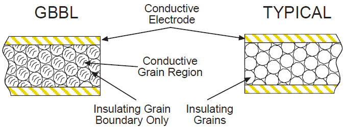
Johanson Technology's new "GBBL" microwave broadband capacitors feature high capacitance per case size without sacrificing the temperature stability associated with high dielectric constant materials. GBBL broadband capacitors feature a proprietary X7R composition which is manufactured by a two step, atmospheric controlled sintering process. The resulting microstructure is composed of a conducting titanate ceramic grain in contact with an insulating Grain Boundary Layer (GBBL). The insulating boundary layer acts as a very thin dielectric. The process control of the boundary thickness, in conjunction with the conductive grain size, provides the cumulative effect of a very high, yet stable, dielectric constant.
Key Features:
- GBBL Dielectric Yields High Volumetric Efficiency
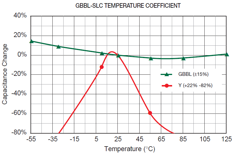
- Stable Temperature Coefficient: ±15% Max (-55°C to 125°C)
- Reduced Microphonics
- Offered With or Without Borders
- Thin Film TiW/Au or TiW/Ni/Au Electrodes
- RoHS
Broadband Capacitors Information
Dielectric Characteristics
| TEMPERATURE COEFFICIENT: | ±15%, -55 to 125°C | DIELECTRIC STRENGTH: | 2.5 X WVDC Min., 50 mA max | |
| VOLTAGE RATING: | 16 - 50 VDC | TEST PARAMETERS: | 1kHz ±50Hz, 1.0±0.2 VRMS, 25°C | |
| DISSIPATION FACTOR: | .025 (2.5%) max | INSULATION RESISTANCE: | 10 G Typ. | |
| AVAILABLE CAPACITANCE: | 68 pF - 3900 pF |
Size and Capacitance Selection
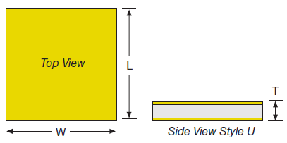 Border Style "U" Configuration |
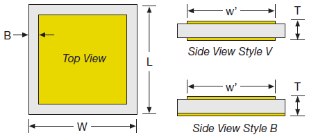 Border Style "V" & "B" Configuration |
| BORDER | U | V, B | U | V, B | U | V, B | U | V, B | |
|---|---|---|---|---|---|---|---|---|---|
| SIZE | 01 | 02 | 03 | 04 | |||||
| W | in | .015 ±.005 | .025 ±.005 | .035 ±.005 | .050 ±.010 | ||||
| (mm) | (0.38 ±.13) | (0.64 ±.13) | (0.89 ±.13) | (1.27 ±.25) | |||||
| L | in | .015 ±.005 | .025 ±.005 | .035 ±.005 | .050 ±.010 | ||||
| (mm) | (0.38 ±.13) | (0.64 ±.13) | (0.89 ±.13) | (1.27 ±.25) | |||||
| T | in | .007 ± .002 | .007 ± .002 | .007 ± .002 | .007 ± .002 | ||||
| (mm) | (0.18 ± .05) | (0.18 ± .05) | (0.18 ± .05) | (0.18 ± .05) | |||||
| B | in | n/a | .002±.001” | n/a | .002±.001” | n/a | .002±.001” | n/a | 002±.001” |
| (mm) | (0.05±.03) | (0.05±.03) | (0.05±.03) | (0.05±.03) | |||||
| Capacitance pF Code |
U01 | V01 B01 |
U02 | V02 B02 |
U03 | V03 B03 |
U04 | V04 B04 |
|
| 75 | 750 | 50V | 50V | ||||||
| 82 | 820 | 50V | 50V | ||||||
| 100 | 101 | 50V | 50V | ||||||
| 120 | 121 | 50V | 50V | ||||||
| 150 | 151 | 50V | 50V | ||||||
| 220 | 221 | 25V | 25V | ||||||
| 270 | 271 | 25V | 16V | 50V | |||||
| 330 | 331 | 16V | 16V | 50V | 50V | ||||
| 390 | 391 | 16V | 16V | 50V | 50V | ||||
| 390 | 391 | 16V | 16V | 50V | 50V | ||||
| 470 | 471 | 16V | 50V | 25V | |||||
| 560 | 561 | 25V | 25V | ||||||
| 680 | 681 | 25V | 16V | 50V | |||||
| 750 | 751 | 16V | 16V | 50V | 50V | ||||
| 820 | 821 | 16V | 16V | 50V | 25V | ||||
| 1000 | 102 | 16V | 16V | 25V | 25V | ||||
| 1200 | 122 | 16V | 25V | 16V | 50V | ||||
| 1500 | 152 | 16V | 16V | 50V | 50V | ||||
| 1800 | 182 | 16V | 16V | 50V | 25V | ||||
| 2200 | 222 | 16V | 25V | 25V | |||||
| 2700 | 272 | 25V | 16V | ||||||
| 3300 | 332 | 16V | 16V | ||||||
| 3900 | 392 | 16V | |||||||
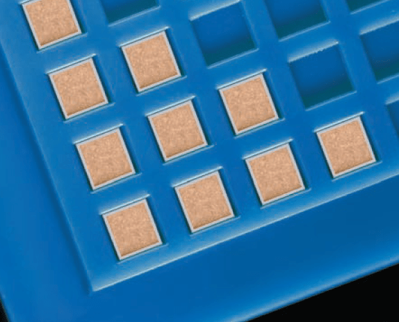
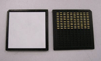
Waffle Pack Opening Procedure
Discrete Devices packaged in Waffle Packs normally have room to move around within the pocket. Sometimes parts may stick to the paper insert usually placed between the top of the package and the lid. Parts can easily jump out of an open package subject to small vibrations, static charge or strong airflow. Smaller parts are more susceptible to jumping out of, or being blown out of, the pockets of an open waffle pack. To minimize the risk of losing parts, implementation of the following procedures at incoming inspection or at the point of use on the production floor are recommended.
1. Holding the clip with one hand, use the thumb of one hand and thumb and fingers of the other hand to slide the waffle “tray” and the lid out of the clip without allowing the tray and lid to separate. JTI recommends using gloves when opening discrete device packaging.
2. Carefully slide the tray and lid onto a flat surface without allowing the tray and lid to separate. The work area should have static reduction measures in place such as a grounded, dissipative work surface and ionizing fans. It should be free of strong drafts, particularly for parts smaller than 20 mil X 20 mil (0.5 X 0.5 mm).
3. Hold down two diagonal corners with one hand to keep the lid securely on top of the tray and use tweezers or another small tool to gently tap the lid at the two exposed corners and the center of the lid. This should cause any parts that may be stuck to the insert to fall back into the cavity.
4. Carefully lift the lid straight up to remove from the tray, turn the lid upside down and place it on the flat surface next to the tray. Parts should be removed from the package with a vacuum pen with an appropriate end tip. CAUTION: Tweezers can cause damage to discrete components.
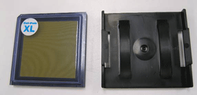
NOTE: An alternative to Waffle Packs are Gel-Paks. These packages will hold discrete devices more securely. The tradeoff is that a vacuum fixture may be required for easy removal from the surface and there may be an incrementally higher cost for the Gel-Pak.
Alternate part numbering for Rectangular parts
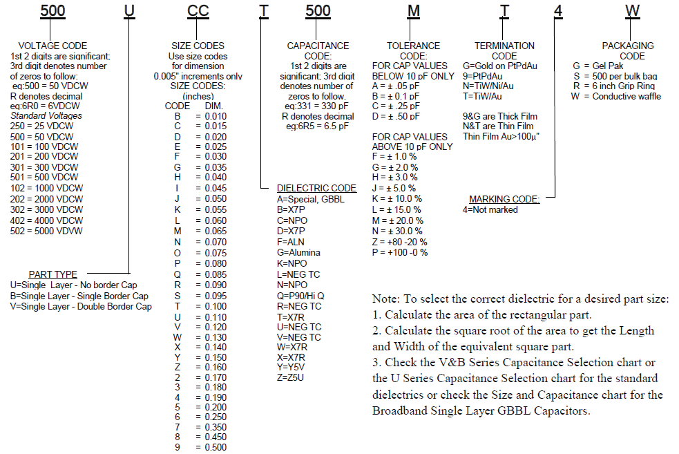
How to Order
Valid options are shown except for Capacitance
A typical PN is S2AU250A471K1S1001B. This part number breaks down as follows:
Capacitors Single Layer - Dual Bord, .025 x .025", GBBL, 25V, 470pF±10%, TiW/Ni/Au, Bulk
New Johanson Global Part Number Breakdown
* Not all combinations create valid part numbers, ask our Apps Engineering Team for assistance creating a valid part number Request for assistanceClick below to see the new Global Part Number Reference Chart for this product
Legacy How to Order Information