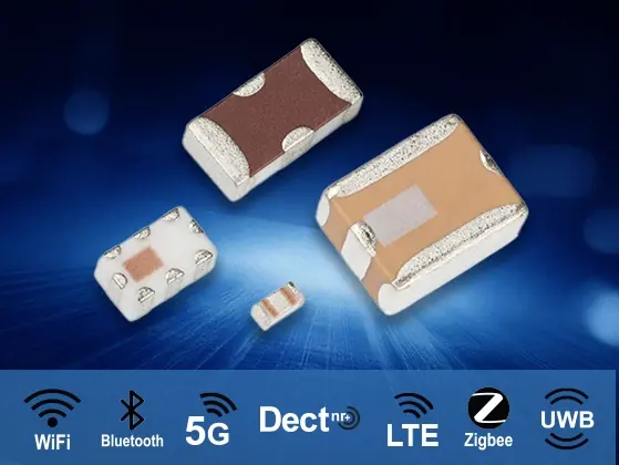
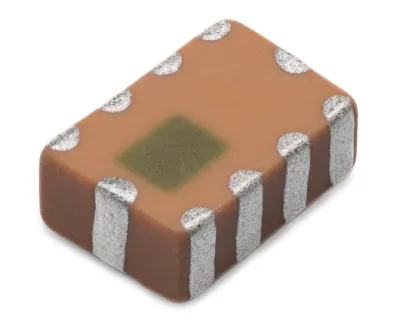
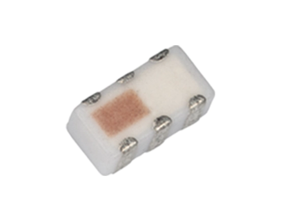
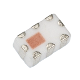
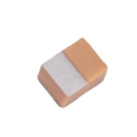
Integrated Passive Components (IPCs)
Key Features:
- Custom Solutions
- Wide Range of RF Bands: 400MHz to 30GHz
- LTCC (Low Temp Co-Fired Ceramics) Based Designs
- Low Insertion Loss
- Miniature Size / Ultra-Low Profiles, Surface Mount (SMT)
- Extremely Temperature Stable
- RoHS/REACH Compliant Standard, Use no Suffix
- AEC-Q200 Automotive Qualification (as required)
List of Silver Leaded IPCs: https://www.johansontechnology.com/tech-notes/silver-leaded-components-soldering-profile/
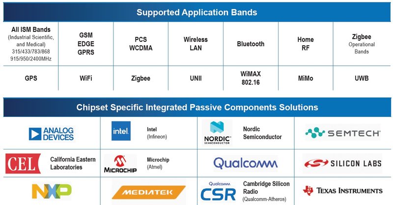
Our advanced solutions cover a wide range of supported application bands, including all ISM bands (315/433/783/868/915/950/2400 MHz), GSM, EDGE, GPRS, PCS, WCDMA, Bluetooth, WiFi, Zigbee, and more.
We provide Chipset-specific Integrated Passive Components designed for industry-leading chipsets from manufacturers such Analog Devices, Intel, Nordic Semiconductor, Semtech, Qualcomm, Texas Instruments, and many others.
Whether you're developing for wireless LAN, GPS, MiMo, or UWB, our components are designed to optimize performance across the board.
Band Pass Filters
RF band pass filters for Wi-Fi, cellular, GNSS, satellite, and IoT applications, delivering reliable frequency isolation and improved signal integrity …
Learn more about Band Pass FiltersBaluns
Integrated RF Baluns for Wireless Front-End Design and Impedance Matching
Johanson Technology’s Integrated RF Baluns are designed to simplify RF …
Learn more about BalunsCouplers
RF Couplers for Wireless, Power Amplifier, and High-Frequency Applications
Johanson Technology offers a wide range of RF couplers designed for …
Learn more about CouplersDiplexers & Triplexers
Integrated RF Diplexers and Triplexers for Wireless Front-End Design
Key Features:
- Integrated Design: Combines multiple functions into a single component …
High Pass Filters

RF High Pass Filters for High-Frequency Signal Conditioning
Key Features:
- Precision Design: Offers accurate high-frequency signal filtering.
- Compact Size: Available …
Low Pass Filters

RF Low Pass Filters for Harmonic Suppression and Signal Conditioning
Key Features:
- High Precision: Delivers accurate low-frequency signal filtering.
- Compact …
Power Dividers
RF Power Dividers for Wireless and RF Systems
Key Features:
- Efficient Performance: Delivers precise signal division with minimal insertion loss.
- …
Balun-Filter Combinations

Integrated RF Balun-Filter Combinations for Compact Wireless Front-End Design
Johanson Technology’s Integrated Balun-Filter Combos combine balun functionality with harmonic filtering …
Learn more about Balun-Filter Combinations