Chip Balun: Definitions & Measurements Methodology
Understand chip balun terminology, key performance specs, and S-parameter test methods.
A must-read for RF design and wireless communication engineers.
Differential circuits are becoming more widely used in RF circuits for the same reason that they have been used for years in lower frequency circuits. The benefits of using differential circuits include immunity to electromagnetic interference, power supply noise and ground noise, even-order harmonic suppression, and tolerance to less than perfect RF grounds. Thus, baluns are employed in many modern circuit designs.
A balun (a compound term meaning "balanced-unbalanced") is a passive bidirectional device designed to transform impedance. A balun consists of an "unbalanced" port converted to two "balanced ports". The unbalanced port can be either the input or the output as the device’s balanced ports would conversely be either the output or the input. Balanced ports allow components with balanced I/Os to be used, and allow them to be coupled to/from components with unbalanced I/Os, thus allowing superior noise immunity due to the balanced system architecture.
Most commonly, baluns are designed with the unbalanced port being a 50 ohm impedance. The most common transformation ratios are 1:1 (50:50), 1:2 (50:100), and 1:4 (50:200).
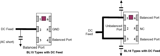
Most Johanson Technology baluns have DC bias capability. Refer to the individual specification sheet to determine if an individual balun has this capability. This will be at pin # 2 for most BL15 parts, and at pins # 1 & # 3 for BL18 parts. When a DC bias is applied, the bias will appear at both balanced ports. Be certain to RF bypass the appropriate pins when a DC bias is applied so that they look like a RF ground (See figure 1). If no DC bias is to be used, these pins can be directly grounded, or, for some models, kept as an open ( again, check with the individual specification sheet). The unbalanced pin is DC isolated from the DC bias pins and from the balanced ports.
Figure 1:
A bypass capacitor is needed for DC bias applications
It is difficult to provide accurate characterization of baluns for two primary reasons: it is a 3-port device, and the input an output typically have different impedances from each other, making network analyzer calibration more difficult. In order to characterize baluns, Johanson Technology uses two types of test boards. The "A" type test board is designed to have two baluns of the same part number mounted on it in a back-to-back configuration. It has two 50 ohm I/Os whereby one I/O is connected to the unbalanced port of one of the baluns, and the other I/O is connected to the unbalanced port of the other balun. The balanced ports of one of the baluns are directly connected to the balanced ports of the other balun. The through insertion loss can be determined by dividing by two.
The "B" type test board is designed to have one balun mounted on it and has three I/Os (one unbalanced, two balanced).
Edge mounted SMA connectors can be supplied with either board if desired. Please contact Johanson Technology applications engineering for more information.
Figure 2 (Hookup for BL14 types):
The following tests can be done with an "A" type board. For the return loss test, a 50, 100, or 200 ohm chip resistor (value dependent on the tranformation ratio of the DUT) is mounted between the balanced ports in place of the second balun.
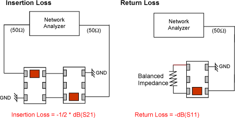
Figure 3 (Hookup for BL14 types):
The Amplitude and Phase Imbalance are measured in a setup per the following: The "B" style board can be used for this measurement. The values of the resistors are 25, 50, or 100 ohm chip resistors (values being dependent on the transformation ratio of the D.U.T.). The component schematically shown as a switch represents switching done in test either by a 3-Port Network Analyzer, or by hardwiring in each respective position.
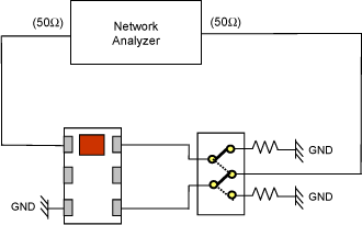
Figure 4 (Hookup for BL15 types):
The following tests can be done with an "A" type board. For the return loss test, a 50, 100, or 200 ohm chip resistor (value dependent on the tranformation ratio of the DUT) is mounted between the balanced ports in place of the second balun.
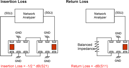
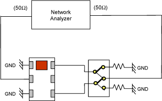
Figure 5 (Hookup for BL15 types):
The Amplitude and Phase Imbalance are measured in a setup per the following: The "B" style board can be used for this measurement. The values of the resistors are 25, 50, or 100 ohm chip resistors (values being dependent on the transformation ratio of the D.U.T.). The component schematically shown as a switch represents switching done in test either by a 3-Port Network Analyzer, or by hardwiring in each respective position.
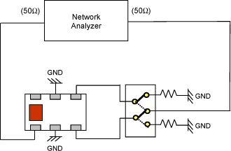
Figure 6 (Hookup for most BL18 types):
The following tests can be done with an "A" type board. For the return loss test, a 50, 100, or 200 ohm chip resistor (value dependent on the tranformation ratio of the DUT) is mounted between the balanced ports in place of the second balun.

Figure 7 (Hookup for most BL18 types):
The Amplitude and Phase Imbalance are measured in a setup per the following: The "B" style board can be used for this measurement. The values of the resistors are 25, 50, or 100 ohm chip resistors (values being dependent on the transformation ratio of the D.U.T.). The component schematically shown as a switch represents switching done in test either by a 3-Port Network Analyzer, or by hardwiring in each respective position.
The difficulties of measuring balun characteristics and the methodologies used by Johanson Technology to test them have been detailed.