Trimming Characteristics of LASERtrim® Chip Capacitor
This note discusses the relationship of current handling, power dissipation, applied voltage and the maximum rated voltage of a multi-layer ceramic capacitor. Either the maximum voltage rating or the maximum power dissipation of the part limits the maximum current through a capacitor. The capacitance value and the operating frequency determine which of the two becomes the governing limit. For lower values of capacitance at a given frequency, or lower frequencies at a given capacitance, the voltage limitation is generally reached before the power dissipation limitation.
Introduction:
LASERtrim® chip capacitors are laser adjustable surface mount multi-layer ceramic (MLCC) capacitors intended for active trimming applications in various RF circuits. They offer the end-user the advantages of reduced tuning time, increased tuning resolution and accuracy, and high reliability in functional tuning applications. To fully realize all of the these benefits requires careful set-up and control of the laser trimming process parameters.
Construction Overview:
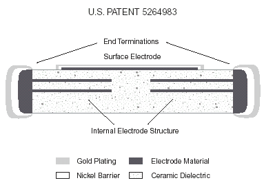
The device’s construction is similar to that of a conventional MLCC with the addition of an exposed surface electrode (See Fig. 1). This surface electrode interacts with internal buried electrodes and determines the initial capacitance prior to trimming. The monolithic body is a proprietary combination of Class I dielectric and electrode material exhibiting a stable temperature coefficient and excellent RF characteristics. This construction is hermetic to solvent, flux, and moisture intrusion. Nickel barrier terminations minimize metal migration and leaching effects associated with conventional surface mount soldering processes. This device offers increased post-trim reliability over conventional mechanical trimmers, in part, because there are no mechanical parts to be affected by flux, cleaning agents, moisture, thermal shock, vibration, etc..
Laser Trimming Process:
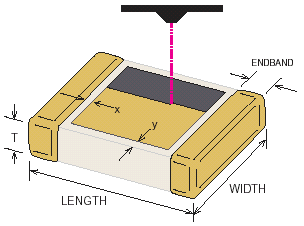
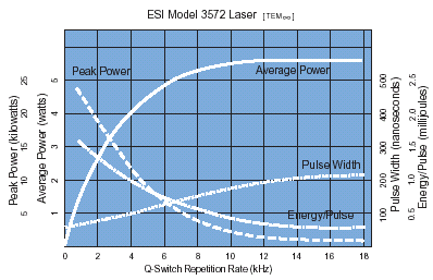
The capacitance of the LASERtrim® decreases as the surface electrode is removed by vaporizing it with a controlled laser beam. The best direction of trimming is shown in Fig. 2. Other methods are not recommended since they may lead to uneven thermal stress (possibly thermal cracks) as well as reduced electrical performance. This study was conducted using an ESI model 3572 which is a Q-switched Neodymium YAG (Yttrium Aluminum Garnet) laser having a maximum average power of 6 watts and a wavelength of 1064 nanometers. The laser beam has a spot size of 40-50 µm and the pulse (Q-rate) can be switched from DC to 20 kHz. The relationship between peak power, average power, pulse width and Q-switch repetition rate parameters of the 3572 is shown below for reference.
Laser parameters should be chosen such that the following occurs:
- The surface electrode is completely and cleanly removed.
- Typical ceramic penetration is .8 to 1.1 mils measured from the top electrode.
- The beam speed and the rep-rate provide 40-60% overlap.
- The heat dissipated by the capacitor is minimal.
The following alignments are also critical to successful trimming:
- The laser beam should be in focus or operating within its depth of field (typically ±25 mils). Operating outside this window decreases the laser power density rapidly, resulting in incomplete electrode removal.
- Beam travel beyond the trim-pad should be minimized. Allowing the laser to touch the end terminations of the capacitor should be avoided as this may result in adverse electrical behavior such as low insulation resistance or increased ESR. Breaching the barrier termination may also provide a means for silver migration to occur resulting in potential long term reliability problems.
- The beam should be aligned such that all trimming occurs on the component. Even an out of focus beam can burn the surface of circuit boards and damage the underlying structure.
Generally, a high peak power with low average power is preferred for capacitor trimming. In production environments the emphasis to increase efficiencies may tempt one to simply increase the beam speed in order to obtain faster trimming times. This adjustment must be compensated by increasing the rep-rate in order to maintain the 40-60% overlap required for complete removal of the electrode. When the rep-rate is increased, average power increases and peak power decreases. Extreme care is advised when trimming with rep-rates greater than 3 kHz as this may result in sufficient average laser power to thermally induce micro-cracks in the capacitor due to the amount of heat which the capacitor must dissipate. Insufficient peak power may result in incomplete vaporization of the electrode causing poor electrical performance such as high ESR, low Q, low IR, or negligible capacitance change with respect to the % area trimmed.
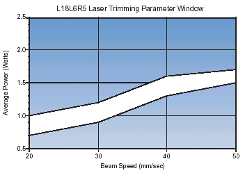
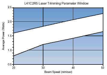
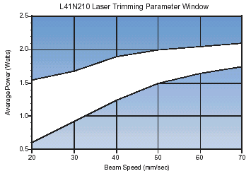
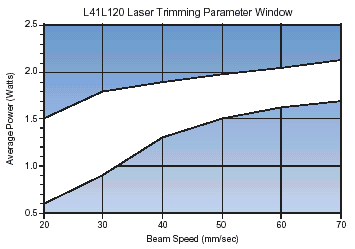
A study was conducted to characterize acceptable laser trimming parameter windows among four different LASERtrim® models. Samples of each model were trimmed under various trimming parameters and then checked for electrical performance and acceptable penetration depth. Beam speed was selected on the laser and then the Q-switch or repetition rate was set to maintain a 40-60% “bite size” or pulse overlap. The laser’s average power was then set by adjusting the lamp current while monitoring average power at the work surface with a Bolometer. The scan increment was kept constant at 12.5 µm.
The results are shown in Figures 3,4,5 & 6 below. The optimum laser trimming parameters were found to be dependent upon the individual model’s ceramic characteristics (e.g. each model will have it’s own unique set of optimum trimming parameters.) Lasers with different characteristics would be expected to yield different “safe” parameter windows
Initial Trimming Parameters:
Below are conservative start-up parameters for uncharacterized laser equipment and/or different device models.
- Laser rep-rate: 1 kHz
- Laser beam speed: 20 mm/s
- Laser average power: 1 watt
- Scan-in increment: 12.5 µm
Summary:
Consistent laser power control is the one of the most important keys to successful and reliable trimming. A laser’s average power is controlled by the lamp current. The actual emitted laser power at a particular lamp current setting may vary significantly due to several factors. Lamp ageing is one of the most critical of these factors. The lamp ageing factor will also vary between laser stations depending upon station usage and the type of laser. In order to maintain trimming consistency between production lots and laser stations a closed loop average power monitoring system or on-line Statistical Process Control for laser power is mandatory.
For more information please contact our Application Engineers.
