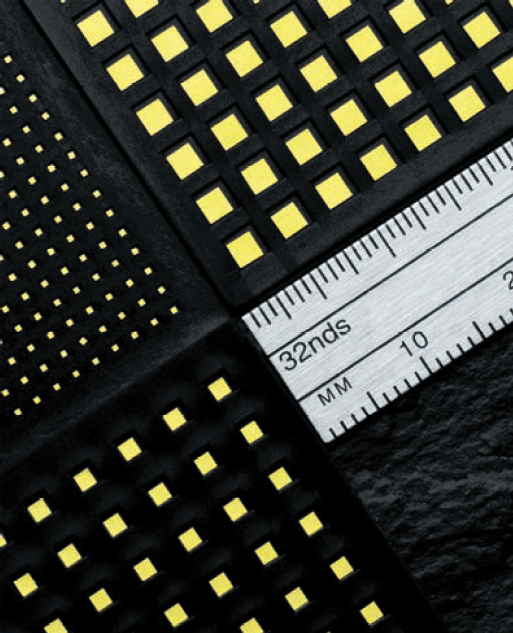
Microwave SLC Single Layer Capacitors
A Single Layer Capacitor is a rectangular or square piece of dielectric material with metallization across the top and bottom of the ceramic. These metallized layers form a bottom electrode contact, and top electrode contact (top contact normally formed using a wirebond).
Johanson Single Layer capacitors are offered in a wide range of dielectrics for very high frequency applications.
Available in sizes from 0.25 x 0.25mm (10 x 10mil) to 5 x 5mm (200 x 200mil), these single layer capacitors are used in military infrastructure and industrial markets.
In addition to their excellent performance, reliability and consistency in volume production has been the focus.
Key Features:
- Ceramic SLC Low Profile Devices Exhibit Very High-Q / Low Insertion Loss, SRFs to 50 GHz
- Thin film gold electrodes provide superior wire bonding & die attach performance
- Four SLC Device Types to Fit Many Applications:
- Standard (Die) SLCs
- Border SLCs
- Bar SLC Arrays
- Custom SLC Products
- RoHS - Available on all dielectrics
- Custom sizes are available - please consult factory
Applications:
- Microwave Integrated Components
- GaAs Integrated Circuits
- RF/Microswave Components
- DC Block, Bypass, Tuning
Microwave SLC Single Layer Capacitors Information
Dielectric
| Dielectric Code | Constant (K) | Temperature Coefficient * | Temperature Range | Dissipation Factor | Insulation Resistance | Test cond. | Available Tolerances |
|---|---|---|---|---|---|---|---|
| C | 23 | 0 ± 30ppm | -55°C to +125°C | ≤ 0.15%@1MHz | >1000 GΩ | 1 | B,C,D (A, <2pF) |
| K | 39 | 0 ± 30ppm | -55°C to +125°C | ≤ 0.15%@1MHz | >1000 GΩ | 1 | B,C,D (A, <2pF) |
| N | 76 | 0 ± 30ppm | -55°C to +125°C | ≤ 0.15%@1MHz | >1000 GΩ | 1 | B,C,D (A, <2pF) (F-K, >10pF) |
| V | 160 | -1500 + 500ppm / -946ppm | -55°C to +125°C | ≤ 0.25%@1MHz | >1000 GΩ | 1 | J,K (B-D) |
| R | 440 | -2200 + 500ppm / -1086ppm | -55°C to +125°C | ≤ 0.25%@1MHz | >1000 GΩ | 1 | J,K (B-D) |
| D | 725 | ± 10% | -55°C to +125°C | ≤ 2.50%@1KHz | >100 GΩ | 2 | K,M |
| B | 1410 | ± 10% | -55°C to +125°C | ≤ 2.50%@1KHz | >100 GΩ | 2 | K,M |
| W | 2300 | ± 15% | -55°C to +125°C | ≤ 2.50%@1KHz | >100 GΩ | 2 | K,M |
| X | 3150 | ± 15% | -55°C to +125°C | ≤ 2.50%@1KHz | >100 GΩ | 2 | K,M |
| T | 4100 | ± 15% | -55°C to +125°C | ≤ 2.50%@1KHz | >100 GΩ | 2 | K,M |
| Z | 8500 | +22% -56% | +10°C to +85°C | ≤ 4.00%@1KHz | >10 GΩ | 2 | M,Z |
| Y | 15000 | +22% -82% | -30°C to +85°C | ≤ 4.00%@1KHz | >10 GΩ | 2 | M,Z |
| Voltage Rating: |
50&100 WVDC
|
|---|---|
| Dielectric Strength: |
2.5 x WVDC min, 25°C, 50 mA max
|
| Test Conditions: |
1) 1.0±0.2 VRMS @ 1MHz, 25°C
2) for values ≤ 100pF: 1.0±0.2 VRMS @ 1MHz, 25°C; for ALL other Values: 1.0±0.2 VRMS @1KHz,25°C |
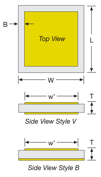
V & B-Series (Borders)
| SIZE | V10 | V12 | V15 | V20 | V25 | V30 | V40 | V50 |
|---|---|---|---|---|---|---|---|---|
| W&L ±.001" | .010 | .012 | .015 | .020 | .025 | .030 | .040 | .050 |
| (mm) | (0.25) | (0.30) | (0.38) | (0.51) | (0.64) | (0.76) | (1.02) | (1.27) |
| w' NOM. | .010 | .007 | .008 | .011 | .016 | .020 | .026 | .036 .044 |
| (mm) | (0.17) | (0.20) | (0.28) | (0.41) | (0.51) | (0.66) | (0.91) | (1.12) |
| B ±.001" | .001* | .001* | .002 | .002 | .002 | .002 | .002 | .003 |
| (mm) | (0.025)* | (0.025)* | (0.051) | (0.051) | (0.051) | (0.051) | (0.051) | (0.076) |
| T .002" | NOM. 0.004" ~ 0.008" | |||||||
| (mm) | (NOM. 0.10 ~ 0.20) | |||||||
|
*Min Border 0.0005"
Contact factory for other sizes, values or configurations |
||||||||
Recessed SLC electrode borders help prevent shorting from conductive epoxy squeeze-up and aid visual recognition equipment. The V-Series SLCs feature dual borders (top & bottom) while the B-Series SLCs feature a single border (top-only.)
| Cap. | V10 100V | V12 100V | V15 100V | V20 100V | V25 100V | V30 100V | V40 100V | V50 100V | |
|---|---|---|---|---|---|---|---|---|---|
| Value | Code | ||||||||
| 0.1 | 0R1 | C | C | C | |||||
| 0.2 | 0R2 | N | K | C | C | ||||
| 0.3 | 0R3 | N | N | K | C | C | |||
| 0.4 | 0R4 | V | N | N | K | C | |||
| 0.5 | 0R5 | V | N | N | K | C | C | ||
| 0.6 | 0R6 | V | V | N | K | K | C | ||
| 0.7 | 0R7 | V | V | V | N | K | C | ||
| 0.8 | 0R8 | R | V | V | N | K | C | ||
| 0.9 | 0R9 | R | V | V | N | K | C | C | |
| 1.0 | 1R0 | R | V | V | N | K | K | C | |
| 1.1 | 1R1 | R | R | V | N | N | K | C | |
| 1.2 | 1R2 | L | R | V | N | N | K | C | |
| 1.3 | 1R3 | L | R | R | N | N | K | C | |
| 1.4 | 1R4 | L | R | R | N | N | K | C | C |
| 1.5 | 1R5 | L | R | R | V | N | K | C | C |
| 1.6 | 1R6 | D | R | R | V | N | K | K | C |
| 1.7 | 1R7 | D | R | R | V | N | K | K | C |
| 1.8 | 1R8 | D | L | R | V | N | K | K | C |
| 1.9 | 1R9 | D | L | L | V | N | N | K | C |
| 2.0 | 2R1 | D | L | L | V | N | N | K | C |
| 2.1 | 2R1 | D | L | L | V | N | N | K | C |
| 2.2 | 2R2 | D | L | L | V | V | N | K | C |
| 2.4 | 2R4 | D | L | L | V | V | N | K | K |
| 2.7 | 2R7 | D | D | L | V | V | N | K | K |
| 3.0 | 2R0 | B | D | D | L | V | N | K | K |
| 3.3 | 3R3 | B | D | D | L | V | N | N | K |
| 3.6 | 3R6 | B | D | D | L | V | N | N | K |
| 3.9 | 3R9 | B | D | D | L | V | V | N | K |
| 4.3 | 4R3 | B | D | D | L | R | V | N | K |
| 4.7 | 4R7 | B | B | D | L | R | V | N | K |
| 5.1 | 5R1 | B | B | D | L | R | V | N | K |
| 5.6 | 5R6 | B | B | B | L | R | V | N | N |
| 6.2 | 6R2 | W | B | B | D | R | V | V | N |
| 6.8 | 6R8 | W | B | B | D | R | V | V | N |
| 7.5 | 7R5 | W | B | B | D | L | R | V | N |
| 8.2 | 8R2 | W | W | B | D | L | R | V | N |
| 9.1 | 9R1 | W | W | W | D | D | R | V | N |
| 10 | 100 | X | W | W | D | D | L | V | V |
| 12 | 120 | X | W | W | B | D | L | R | V |
| 15 | 150 | T | X | X | B | D | L | R | V |
| 18 | 180 | T | X | X | B | D | D | R | R |
| 20 | 200 | T | T | X | B | B | D | L | R |
| 22 | 220 | Z | T | T | B | B | D | L | R |
| 27 | 270 | Z | T | T | W | B | D | D | L |
| 33 | 330 | Y | Z | Z | W | B | B | D | L |
| 39 | 390 | Y | Z | Z | X | W | B | D | L |
| 47 | 470 | Y | Z | Z | X | W | B | D | D |
| 50 | 500 | Y | Y | Z | X | W | B | D | D |
| 51 | 510 | Y | Y | Z | T | X | B | D | D |
| 56 | 560 | Y | Y | Y | T | X | B | B | D |
| 68 | 680 | Y | Y | T | X | W | B | D | |
| 82 | 820 | Y | Y | Z | T | W | B | D | |
| 100 | 101 | Y | Z | T | X | W | B | ||
| 120 | 121 | Z | T | X | W | B | |||
| 150 | 151 | Y | Z | T | X | W | |||
| 180 | 181 | Y | Z | T | T | W | |||
| 200 | 201 | Y | Z | T | T | X | |||
| 220 | 221 | Y | Z | T | X | ||||
| 270 | 271 | Y | Z | T | X | ||||
| 330 | 331 | Y | Y | Z | T | ||||
| 390 | 391 | Y | Z | T | |||||
| 470 | 471 | Y | Z | T | |||||
| 560 | 561 | Y | Y | Z | |||||
| 680 | 681 | Y | Z | ||||||
| 820 | 821 | Y | |||||||
| 1000 | 102 | Y | |||||||
| 1200 | 122 | Y | |||||||
Color breaks used to highlight changes in dielectric material, letters indicate the specific material.
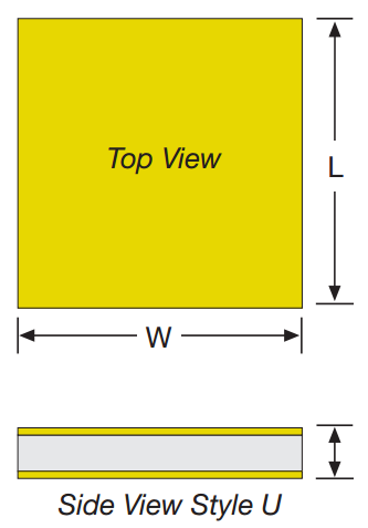
U Series SLC Capacitance Selection (No border)
| CAPACITANCE | U10 | U12 | U15 | U20 | U25 | U30 | U35 | U50 | U70 | U90 | ||||||
|---|---|---|---|---|---|---|---|---|---|---|---|---|---|---|---|---|
| Value | Code | 50V | 50V | 50V | 100V | 50V | 100V | 50V | 100V | 50V | 100V | 50V | 100V | 100V | 100V | 100V |
| 0.1 | 0R1 | C | ||||||||||||||
| 0.2 | 0R2 | K | C | C | ||||||||||||
| 0.3 | 0R3 | N | K | C | K | C | ||||||||||
| 0.4 | 0R4 | N | N | K | K | C | C | C | ||||||||
| 0.5 | 0R5 | U | N | K | N | C | K | C | ||||||||
| 0.6 | 0R6 | V | N | K | N | C | K | C | C | C | ||||||
| 0.7 | 0R7 | V | N | N | N | K | K | C | K | C | C | |||||
| 0.8 | 0R8 | V | U | N | N | K | N | C | K | C | C | |||||
| 0.9 | 0R9 | R | V | N | U | K | N | C | K | C | C | C | ||||
| 1.0 | 1R0 | R | V | N | U | K | N | K | K | C | K | C | C | |||
| 1.1 | 1R1 | R | V | N | V | K | N | K | K | C | K | C | C | C | ||
| 1.2 | 1R2 | R | V | N | V | N | N | K | N | C | K | C | C | C | ||
| 1.3 | 1R3 | R | V | N | V | N | N | K | N | C | K | C | K | C | ||
| 1.4 | 1R4 | L | V | U | V | N | N | K | N | K | K | C | K | C | ||
| 1.5 | 1R5 | L | V | U | V | N | N | K | N | K | K | C | K | C | ||
| 1.6 | 1R6 | L | R | U | V | N | U | K | N | K | N | C | K | C | ||
| 1.7 | 1R7 | L | R | U | V | N | U | K | N | K | N | C | K | C | ||
| 1.8 | 1R8 | L | R | U | R | N | U | N | N | K | N | K | K | C | ||
| 1.9 | 1R9 | L | R | V | R | N | U | N | N | K | N | K | K | C | ||
| 2.0 | 2R1 | D | R | V | R | N | U | N | N | K | N | K | K | K | ||
| 2.1 | 2R1 | D | L | V | R | N | V | N | N | K | N | K | K | K | C | |
| 2.2 | 2R2 | D | L | V | R | U | V | N | U | K | N | K | N | K | C | |
| 2.4 | 2R4 | D | L | V | R | U | V | N | U | K | N | K | N | K | C | |
| 2.7 | 2R7 | D | L | R | L | U | V | N | U | N | N | K | N | K | C | C |
| 3.0 | 2R0 | D | L | R | L | U | V | N | U | N | N | K | N | K | C | C |
| 3.3 | 3R3 | D | L | R | L | V | R | N | V | N | U | K | N | K | C | C |
| 3.6 | 3R6 | D | D | R | L | V | R | U | V | N | U | K | N | K | C | C |
| 3.9 | 3R9 | B | D | R | L | V | R | U | V | N | U | N | N | N | C | C |
| 4.3 | 4R3 | B | D | R | D | V | R | U | V | N | V | N | N | N | C | C |
| 4.7 | 4R7 | B | D | L | D | R | R | U | R | N | V | N | N | N | K | C |
| 5.1 | 5R1 | B | D | L | D | R | R | V | R | U | V | N | U | N | K | C |
| 5.6 | 5R6 | B | D | L | D | R | L | V | R | U | V | N | U | N | K | K |
| 6.2 | 6R2 | B | D | D | D | R | L | V | R | U | V | N | U | N | K | K |
| 6.8 | 6R8 | B | B | D | D | R | L | R | R | V | R | N | V | N | K | K |
| 7.5 | 7R5 | W | B | D | D | R | D | R | L | V | R | U | V | N | K | K |
| 8.2 | 8R2 | W | B | D | B | L | D | R | L | V | R | U | V | N | N | K |
| 9.1 | 9R1 | W | B | D | B | L | D | R | L | V | R | U | R | N | N | N |
| 10 | 100 | X | B | D | B | L | D | R | L | R | L | V | R | V | N | N |
| 12 | 120 | X | W | B | B | D | D | L | D | R | L | V | R | V | N | N |
| 15 | 150 | T | W | B | W | D | B | L | D | R | L | R | L | V | N | N |
| 18 | 180 | T | W | B | W | D | B | D | D | L | D | R | L | V | V | N |
| 20 | 200 | T | X | W | W | D | B | D | D | L | D | R | D | R | V | N |
| 22 | 220 | T | X | W | X | B | B | D | B | L | D | R | D | R | V | N |
| 27 | 270 | Z | T | W | X | B | W | D | B | D | D | L | D | R | V | U |
| 33 | 330 | Z | T | X | T | B | W | B | D | D | B | L | D | L | R | U |
| 39 | 390 | Z | T | X | T | W | X | B | W | D | B | D | B | L | R | V |
| 47 | 470 | Y | Z | T | T | W | X | B | W | D | B | D | B | D | R | V |
| 50 | 500 | Y | Z | T | Z | W | X | B | W | B | B | D | B | D | R | V |
| 51 | 510 | Y | Z | T | Z | W | X | B | W | B | B | D | B | D | R | R |
| 56 | 560 | Y | Z | T | Z | W | T | B | X | B | W | D | B | D | R | R |
| 68 | 680 | Z | Z | Z | X | T | W | X | B | W | B | W | D | L | R | |
| 82 | 820 | Y | Z | Y | T | Z | W | T | B | X | B | X | B | D | R | |
| 100 | 101 | Y | Z | Y | T | Z | X | T | W | X | B | X | B | D | L | |
| 120 | 121 | Y | Y | T | Z | T | T | W | T | W | X | B | D | D | ||
| 150 | 151 | Y | Z | Y | T | Z | X | T | W | X | B | B | D | |||
| 180 | 181 | Y | Z | Y | T | Z | T | T | W | T | W | B | D | |||
| 200 | 201 | Z | Y | Z | Z | T | Z | X | T | W | B | B | ||||
| 220 | 221 | Y | Y | Z | Z | T | Z | X | T | W | B | B | ||||
| 270 | 271 | Y | Z | Y | T | Z | T | Z | X | W | B | |||||
| 330 | 331 | Y | Y | Y | Z | Z | T | Z | X | W | W | |||||
| 390 | 391 | Y | Z | Y | T | Z | T | X | W | |||||||
| 470 | 471 | Y | Z | Y | Z | Y | T | X | W | |||||||
| 560 | 561 | Y | Y | Z | Y | T | T | X | ||||||||
| 680 | 681 | Y | Z | Y | Z | T | X | |||||||||
| 820 | 821 | Y | Z | T | X | |||||||||||
| 1000 | 102 | Y | Z | T | T | |||||||||||
| 1200 | 122 | Y | Z | T | ||||||||||||
| 1500 | 152 | Y | Y | Z | ||||||||||||
| 1800 | 182 | Y | Z | |||||||||||||
| 2000 | 202 | Y | Z | |||||||||||||
| 2500 | 252 | Y | Y | |||||||||||||
| 4000 | 402 | Y | ||||||||||||||
Color breaks used to highlight changes in dielectric material, letters indicate the specific material.
V-Series & B-Series Mechanical Characteristics
| Size | V10 | V12 | V15 | V20 | V25 | V30 | V40 | V50 |
|---|---|---|---|---|---|---|---|---|
| W&L ±.001" (mm) | .010 (0.25) | .012 (0.30) | .015 (0.38) | .020 (0.51) | .025 (0.64) | .030 (0.76) | .040 (1.02) | .050 (1.27) |
| W' NOM. (mm) | .008 (0.20) | .010 (0.25) | .011 (0.28) | .016 (0.41) | .020 (0.51) | .026 (0.66) | .036 (0.91) | .044 (1.12) |
| B ±.001" (mm) | .001* (0.025) | .001* (0.025) | .002 (0.51) | .002 (0.51) | .002 (0.51) | .002 (0.51) | .002 (0.51) | .003 (0.76) |
| T ±.001" (mm) | .006 (0.15) | .006 (0.15) | .006 (0.15) | .006 (0.15) | .006 (0.15) | .006 (0.15) | .006 (0.15) | .006 (0.15) |
|
*Min Border 0.0005" Contact factory for other sizes, values or configurations |
||||||||
| Size | U10 | U12 | U15 | U20 | U25 | U30 | U35 | U50 | U70 | U90 |
|---|---|---|---|---|---|---|---|---|---|---|
| W +.001" -.003" (mm) |
.010 (0.25) |
.012 (0.30) |
.015 (0.38) |
.020 (0.51) |
.025 (0.64) |
.030 (0.76) |
.035 (0.89) |
.050 (1.27) |
.070 (1.78) |
.090 (2.29) |
| L MAX. (mm) |
.012 (0.30) |
.015 (0.38) |
.020 (0.51) |
.025 (0.64) |
.030 (0.76) |
.035 (0.89) |
.040 (1.02) |
.060 (1.52) |
.080 (2.03) |
.100 (2.54) |
| T ±.002" (mm) |
NOM. 0.004" ~ 0.008" (NOM. 0.10 ~ 0.20) |
|||||||||
| Contact factory for other sizes, values or configurations | ||||||||||
SLC Temperature Characteristics
Metallization Characteristics
| Metallization Type | TiW/Au (Titanium-Tungsten/Gold) | TiW/Ni/Au (Titanium-Tungsten/Nickel/Gold) |
|---|---|---|
| Termination Code | T | N |
| Attachment Compatibility | Wire / Ribbon Bonding Silver or Gold Conductive Epoxy Au/Ge or Au/Si Eutectic Preform Excellent High Temperature Resistance (400°C) Unsuitable for Pb/Sn or Au/Sn Soldering |
Pb/Sn or Au/Sn Soldering Au/Sn Eutectic Preform Moderate High Temp. Resistance (325°C) Long term high temperature may cause Ni diffusion and wire bond problems on Au/Ge |
SLC thick-film terminations ( legacy codes "G" and "9") are still supported. Contact the factory for compatibility information.
Environmental Characteristics
| Bond Strength | Exceeds MIL-S-883, Meth. 2011 | Vibration: | MIL-S-202, Meth. 204-G, (30g, 10-2000 Hz) |
|---|---|---|---|
| Shear Strength | Exceeds MIL-S-883, Meth. 2019 | Burn-In/Life Test: | MIL-S-202, Meth. 108, A/F |
| Solder Heat Resistance | MIL-S-202, Meth. 210-C, (260±5°C, 5 sec.) | Low Voltage Humidity: | Mil-C-49464, Para. 3.17 |
| Solderability: | MIL-S-202, Meth. 208, (245±5°C, 5 sec.) | Barometric Pressure: | MIL-S-202, Meth. 105, B |
| Shock: | MIL-S-202, Meth. 213-I, (100g, 6 msec.) | Immersion/Salt Spray: | MIL-S-202, Meth. 104, B |
| Thermal Shock: | MIL-S-202, Meth. 107, A, (-55 to +125°C) | Moisture Resistance: | MIL-S-202, Meth. 106 |
Alternative part number for rectangular parts
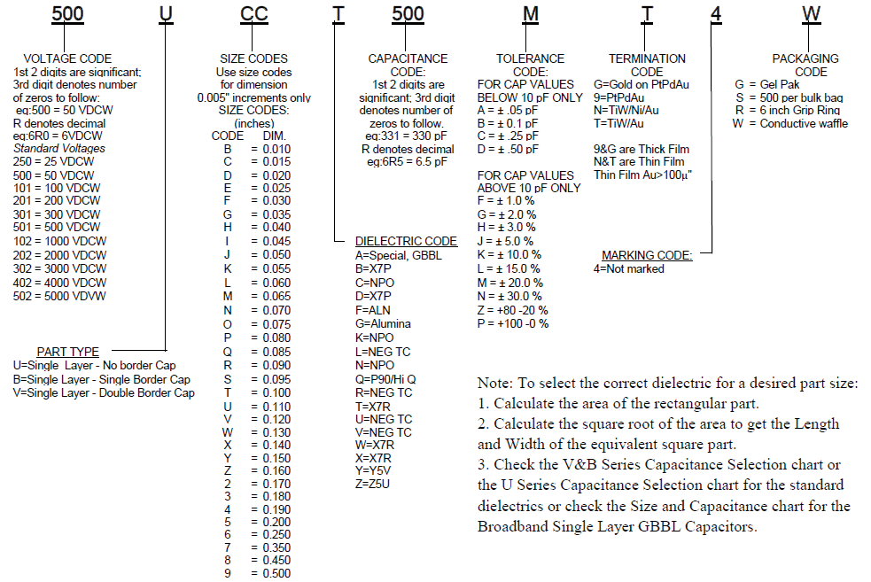
How to Order
Valid options are shown except for Capacitance
A typical PN is S0AL500B100K1S1001W. This part number breaks down as follows:
Capacitors Single Layer - No Bord, .015 x .015", BX, 50V, 10pF±10%, TiW/Ni/Au, Waffle Pack
New Johanson Global Part Number Breakdown
* Not all combinations create valid part numbers, ask our Apps Engineering Team for assistance creating a valid part number Request for assistanceClick below to see the new Global Part Number Reference Chart for this product
Legacy How to Order Information