RF Ceramic Chip Inductors
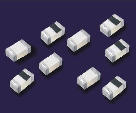
High frequency multi-layer chip inductors feature a monolithic body made of low loss ceramic and high conductivity metal electrodes to achieve optimal high frequency performance. These RF chip inductors are compact in size and feature lead-free tin plated nickel barrier terminations and tape and reel packaging which makes them ideal for small size/high volume wireless applications.
Applications:
- CELL/PCS Modules
- Wireless LAN
- Broadband Components
- RFID
- RF transceivers
- RoHS Compliant (Standard, "V" Code)
- Sn/Pb Terminations Optional ("T" Code)
Product Range Summary
| EIA Size (mm) | SIZE CODE | L RANGE | Q FACTOR (Min.) | SRF(Typ.) | TEMPERATURE |
|---|---|---|---|---|---|
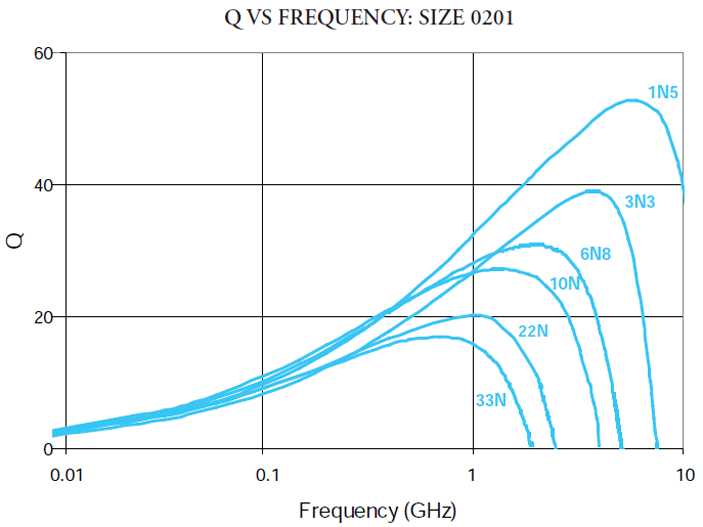
| 0201 (0603) | L-05 | 0.6 - 39 nH | 4 (100 MHz) | >21 GHz (1.0 nH) | -55°C to + 100°C |
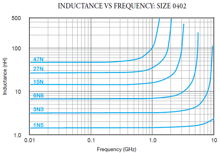
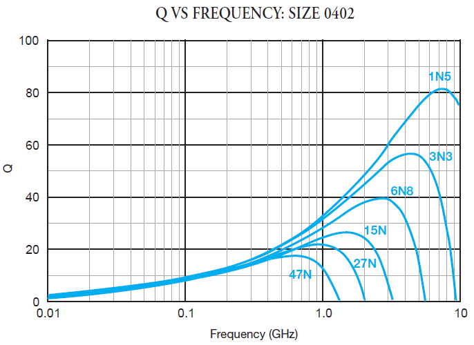
| 0402 (1005) | L-07 | 1.0 - 120 nH | 8 (100 Mhz) | >21 GHz (1.0 nH) | -55°C to + 100°C |
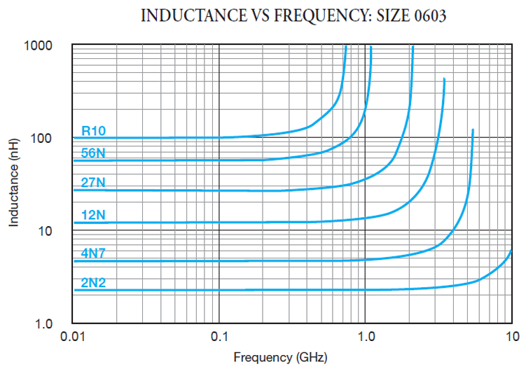
| 0603 (1608) | L-14 | 1.2 - 220 nH | 12 (1 MHz) | >23 GHz (1.0 nH) | -55°C to + 100°C |

RF Ceramic Chip Inductors Information
Mechanical Characteristics
| 0201 (0603) | 0402 (1005) | 0603 (1608) | 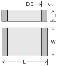 |
||||
| Inches | mm | Inches | mm | Inches | mm | ||
| Length | .024 ±.001" | (0.6 ±.0.03) | .039 ±.004" | (1.00 ±.10) | .063 ±.006" | (1.60 ±.15) | |
| Width | .012 ±.001" | (0.3 ±.0.03) | .020 ±.004" | (0.50 ±.10) | .031 ±.008" | (0.80 ±.15) | |
| Thickness | .012 ±.001" | (0.3 ±.0.03) | .020 ±.004" | (0.50 ±.10) | .031±.008" | (0.80±.15) | |
| End Band | .006 ±.002" | (0.15 ±0.05) | .009 ±.004" | (0.23 ±.10) | .012±.004" | (0.30 ±.20) | |
Inductance Range / Electrical Characteristics
| EIA Size \ Inductor Value |
0201 (L-05) |
0402 (L-07) |
0603 (L-14) |
||
| Inductance | |||||
| nH | Code | Tolerance | |||
| 0.6 | 0N6 | C S |
300 mA | ||
| 0.7 | 0N7 | 300 mA | |||
| 0.8 | 0N8 | 300 mA | |||
| 0.9 | 0N9 | 300 mA | |||
| 1.0 | 1N0 | 300 mA | 300 mA | 300 mA (S only) | |
| 1.2 | 1N2 | 300 mA | 300 mA (S only) | 300 mA (S only) | |
| 1.3 | 1N3 | 300 mA | |||
| 1.5 | 1N5 | 300 mA | 300 mA (S only) | 300 mA (S only) | |
| 1.8 | 1N8 | 300 mA | 300 mA (S only) | 300 mA (S only) | |
| 1.9 | 1N9 | 300 mA | 300 mA (S only) | ||
| 2.0 | 2N0 | 300 mA | 300 mA (S only) | ||
| 2.2 | 2N2 | 300 mA | 300 mA (S only) | 300 mA (S only) | |
| 2.3 | 2N3 | 300 mA | |||
| 2.4 | 2N4 | 300 mA | 300 mA (S only) | ||
| 2.5 | 2N5 | 300 mA | |||
| 2.7 | 2N7 | 300 mA | 300 mA (S only) | 300 mA (S only) | |
| 3.0 | 3N0 | 300 mA | 300 mA (S only) | ||
| 3.3 | 3N3 | K S |
300 mA | 300 mA | 300 mA |
| 3.6 | 3N6 | 300 mA | 300 mA | ||
| 3.7 | 3N7 | 300 mA | 300 mA | ||
| 3.9 | 3N9 | 300 mA | 300 mA | 300 mA | |
| 4.3 | 4N3 | 300 mA | |||
| 4.7 | 4N7 | 300 mA | 300 mA | 300 mA | |
| 5.1 | 5N1 | 300 mA | 300 mA | ||
| 5.6 | 5N6 | 300 mA | 300 mA | 300 mA | |
| 6.2 | 6N2 | 300 mA | |||
| 6.8 | 6N8 | J K |
250 mA | 250 mA | 300 mA |
| 7.5 | 7N5 | 250 mA | |||
| 8.2 | 8N2 | 250 mA | 250 mA | 300 mA | |
| 10 | 10N | 250 mA | 250 mA | 300 mA | |
| 12 | 12N | 250 mA | 250 mA | 300 mA | |
| 13 | 13N | 250 mA | 250 mA | 300 mA | |
| 15 | 15N | 250 mA | 250 mA | ||
| 18 | 18N | 200 mA | 200 mA | 300 mA | |
| 20 | 20N | 200 mA | 200 mA | ||
| 22 | 22N | 200 mA | 200 mA | 300 mA | |
| 23 | 23N | 200 mA | |||
| 27 | 27N | 200 mA | 200 mA | 300 mA | |
| 33 | 33N | 200 mA | 200 mA | 300 mA | |
| 39 | 39N | 200 mA | 150 mA | 300 mA | |
| 43 | 43N | 150 mA | |||
| 47 | 47N | 150 mA | 300 mA | ||
| 56 | 56N | 150 mA | 300 mA | ||
| 68 | 68N | 100 mA | 300 mA | ||
| 82 | 82N | 100 mA | 300 mA | ||
| 100 | R10 | 100 mA | 300 mA | ||
| 120 | R12 | 100 mA | 300 mA | ||
| 150 | R15 | 300 mA | |||
| 180 | R18 | 300 mA | |||
| 220 | R22 | 300 mA | |||
| 270 | R27 | ||||
| 330 | R33 | ||||
| 390 | R39 | ||||
| 420 | R42 | ||||
| 560 | R56 | ||||
| 680 | R68 | ||||
Electrical Specifications: L-05B Series (0201 Polarity Half-Marked Inductors)
| Part Number | Inductance (nH) | Q Min. | Q Typ. | L/Q Freq. (MHz) | RDC (Ω) | S.R.F. (MHz) Typ. | IDC (mA) Max. | |
| Max | Typ. | |||||||
| L-05B1N0SV6T | 1.0 ± 0.3 | 4 | 6 | 100 | 0.12 | 0.07 | 17070 | 300 |
| L-05B1N2SV6T | 1.2 ± 0.3 | 4 | 6 | 100 | 0.15 | 0.11 | 16030 | 300 |
| L-05B1N5SV6T | 1.5 ± 0.3 | 4 | 6 | 100 | 0.18 | 0.11 | 13750 | 300 |
| L-05B1N8SV6T | 1.8 ± 0.3 | 4 | 6 | 100 | 0.22 | 0.12 | 11830 | 300 |
| L-05B2N2SV6T | 2.2 ± 0.3 | 4 | 6 | 100 | 0.26 | 0.16 | 9940 | 300 |
| L-05B2N7SV6T | 2.7 ± 0.3 | 4 | 6 | 100 | 0.32 | 0.17 | 9410 | 300 |
| L-05B3N3_V6T | 3.3 ± 0.3 or ± 10% | 4 | 6 | 100 | 0.38 | 0.21 | 7530 | 300 |
| L-05B3N9_V6T | 3.9 ± 0.3 or ± 10% | 4 | 6 | 100 | 0.45 | 0.31 | 7090 | 300 |
| L-05B4N7_V6T | 4.7 ± 0.3 or ± 10% | 4 | 6 | 100 | 0.50 | 0.35 | 5850 | 300 |
| L-05B5N6_V6T | 5.6 ± 0.3 or ± 10% | 5 | 7 | 100 | 0.60 | 0.40 | 5740 | 300 |
| L-05B6N8_V6T | 6.8 ± 5% or ± 10% | 5 | 7 | 100 | 0.70 | 0.42 | 5130 | 250 |
| L-05B8N2_V6T | 8.2 ± 5% or ± 10% | 5 | 7 | 100 | 0.90 | 0.44 | 4830 | 250 |
| L-05B10N_V6T | 10 ± 5% or ± 10% | 5 | 7 | 100 | 1.20 | 0.45 | 4190 | 250 |
| L-05B12N_V6T | 12 ± 5% or ± 10% | 5 | 7 | 100 | 1.30 | 0.55 | 3690 | 250 |
| L-05B15N_V6T | 15 ± 5% or ± 10% | 5 | 7 | 100 | 1.40 | 0.64 | 3310 | 250 |
| L-05B18N_V6T | 18 ± 5% or ± 10% | 5 | 7 | 100 | 1.50 | 0.78 | 2750 | 200 |
| L-05B22N_V6T | 22 ± 5% or ± 10% | 5 | 8 | 100 | 1.80 | 0.97 | 2510 | 200 |
| L-05B27N_V6T | 27 ± 5% or ± 10% | 5 | 8 | 100 | 2.00 | 1.13 | 2050 | 200 |
| L-05B33N_V6T | 33 ± 5% or ± 10% | 5 | 8 | 100 | 2.30 | 2.07 | 1910 | 200 |
| L-05B39N_V6T | 39 ± 5% or ± 10% | 5 | 8 | 100 | 2.50 | 2.39 | 1600 | 200 |
Electrical Specifications: L-07C Series (0402 Orientation Full-Marking Inductors)
| Part Number | Inductance (nH) | Q Min. | L/Q Freq. (MHz) | RDC (Ω) Max. | S.R.F. (MHz) Typ. | IDC (mA) Max. |
| L-07C1N0_V6T | 1.0 ± 0.2 or 0.3 | 8 | 100 | 0.12 | >15000 | 300 |
| L-07C1N2SV6T | 1.2 ± 0.3 | 8 | 100 | 0.12 | >15000 | 300 |
| L-07C1N5SV6T | 1.5 ± 0.3 | 8 | 100 | 0.13 | >15000 | 300 |
| L-07C1N6SV6T | 1.6 ± 0.3 | 8 | 100 | 0.14 | 15000 | 300 |
| L-07C1N8SV6T | 1.8 ± 0.3 | 8 | 100 | 0.14 | 14000 | 300 |
| L-07C1N9SV6T | 1.9 ± 0.3 | 8 | 100 | 0.15 | 13000 | 300 |
| L-07C2N0SV6T | 2.0 ± 0.3 | 8 | 100 | 0.16 | 12000 | 300 |
| L-07C2N2SV6T | 2.2 ± 0.3 | 8 | 100 | 0.16 | 12000 | 300 |
| L-07C2N4SV6T | 2.4 ± 0.3 | 8 | 100 | 0.16 | 10000 | 300 |
| L-07C2N7SV6T | 2.7 ± 0.3 | 8 | 100 | 0.17 | 9500 | 300 |
| L-07C3N0SV6T | 3.0± 0.3 | 8 | 100 | 0.18 | 9000 | 300 |
| L-07C3N3_V6T | 3.3 ± 0.3 or ± 10% | 8 | 100 | 0.19 | 8500 | 300 |
| L-07C3N6_V6T | 3.6 ± 0.3 or ± 10% | 8 | 100 | 0.21 | 7500 | 300 |
| L-07C3N9_V6T | 3.9 ± 0.3 or ± 10% | 8 | 100 | 0.22 | 7000 | 300 |
| L-07C4N3_V6T | 4.3 ± 0.3 or ± 10% | 8 | 100 | 0.24 | 6000 | 300 |
| L-07C4N7_V6T | 4.7 ± 0.3 or ± 10% | 8 | 100 | 0.24 | 6000 | 300 |
| L-07C5N1_V6T | 5.1 ± 0.3 or ± 10% | 8 | 100 | 0.26 | 5500 | 300 |
| L-07C5N6_V6T | 5.6 ± 0.3 or ± 10% | 8 | 100 | 0.27 | 5400 | 300 |
| L-07C6N2_V6T | 6.2 ± 0.3 or 5% or ± 10% | 8 | 100 | 0.30 | 5200 | 300 |
| L-07C6N8_V6T | 6.8 ± 5% or ± 10% | 8 | 100 | 0.32 | 5000 | 250 |
| L-07C7N5_V6T | 7.5 ± 5% or ± 10% | 8 | 100 | 0.40 | 4600 | 250 |
| L-07C8N2_V6T | 8.2 ± 5% or ± 10% | 8 | 100 | 0.40 | 4600 | 250 |
| L-07C10N_V6T | 10 ± 5% or ± 10% | 8 | 100 | 0.45 | 3700 | 250 |
| L-07C12N_V6T | 12 ± 5% or ± 10% | 8 | 100 | 0.50 | 3200 | 250 |
| L-07C13N_V6T | 13 ± 5% or ± 10% | 8 | 100 | 0.55 | 3100 | 250 |
| L-07C15N_V6T | 15 ± 5% or ± 10% | 8 | 100 | 0.60 | 3100 | 250 |
| L-07C18N_V6T | 18 ± 5% or ± 10% | 8 | 100 | 0.65 | 2900 | 200 |
| L-07C20N_V6T | 20 ± 5% or ± 10% | 8 | 100 | 0.80 | 2100 | 200 |
| L-07C22N_V6T | 22 ± 5% or ± 10% | 8 | 100 | 0.80 | 2100 | 200 |
| L-07C23N_V6T | 23 ± 5% | 8 | 100 | 0.85 | 2000 | 200 |
| L-07C24N_V6T | 24 ± 5% | 8 | 100 | 0.87 | 1900 | 200 |
| L-07C27N_V6T | 27 ± 5% or ± 10% | 8 | 100 | 0.90 | 1900 | 200 |
| L-07C33N_V6T | 33 ± 5% or ± 10% | 8 | 100 | 1.00 | 1600 | 200 |
| L-07C39N_V6T | 39 ± 5% or ± 10% | 8 | 100 | 1.20 | 1400 | 150 |
| L-07C43N_V6T | 43 ± 5% or ± 10% | 8 | 100 | 1.30 | 1300 | 150 |
| L-07C47N_V6T | 47 ± 5% or ± 10% | 8 | 100 | 1.30 | 1200 | 150 |
| L-07C56N_V6T | 56 ± 5% or ± 10% | 8 | 100 | 2.00 | 1100 | 150 |
| L-07C68N_V6T | 68 ± 5% or ± 10% | 8 | 100 | 2.20 | 1000 | 100 |
| L-07C82N_V6T | 82 ± 5% or ± 10% | 8 | 100 | 2.50 | 900 | 100 |
| L-07CR10_V6T | 100 ± 5% or ± 10% | 8 | 100 | 2.50 | 850 | 100 |
| L-07CR12_V6T | 120 ± 5% or ± 10% | 8 | 100 | 2.50 | 750 | 100 |
Electrical Specifications: L-14C Series (0603 Orientation Full-Marking Inductors)
| Part Number | Inductance (nH) | Q Min. | L/Q Freq. (MHz) | RDC ( Ω) Max. | S.R.F. (MHz) Typ. | IDC(mA) Max. |
| L-14C1N0SV4T | 1.0 ± 0.3 | 8 | 100 | 0.10 | >17000 | 300 |
| L-14C1N2SV4T | 1.2 ± 0.3 | 8 | 100 | 0.10 | >17000 | |
| L-14C1N5SV4T | 1.5 ± 0.3 | 8 | 100 | 0.10 | >17000 | |
| L-14C1N8SV4T | 1.8 ± 0.3 | 8 | 100 | 0.15 | 13000 | |
| L-14C2N2SV4T | 2.2 ± 0.3 | 8 | 100 | 0.15 | 12000 | |
| L-14C2N7SV4T | 2.7 ± 0.3 | 8 | 100 | 0.20 | 8600 | |
| L-14C3N3_V4T | 3.3 ± 0.3 or ± 10% | 8 | 100 | 0.25 | 6500 | |
| L-14C3N9_V4T | 3.9 ± 0.3 or ± 10% | 8 | 100 | 0.25 | 6300 | |
| L-14C4N7_V4T | 4.7 ± 0.3 or ± 10% | 8 | 100 | 0.30 | 5400 | |
| L-14C5N6_V4T | 5.6 ± 0.3 or ± 10% | 8 | 100 | 0.30 | 4600 | |
| L-14C6N8_V4T | 6.8 ± 5% or ± 10% | 8 | 100 | 0.35 | 4500 | |
| L-14C8N2_V4T | 8.2 ± 5% or ± 10% | 8 | 100 | 0.40 | 3800 | |
| L-14C10N_V4T | 10 ± 5% or ± 10% | 8 | 100 | 0.45 | 3700 | |
| L-14C12N_V4T | 12 ± 5% or ± 10% | 8 | 100 | 0.50 | 3200 | |
| L-14C15N_V4T | 15 ± 5% or ± 10% | 8 | 100 | 0.55 | 2900 | |
| L-14C18N_V4T | 18 ± 5% or ± 10% | 10 | 100 | 0.60 | 2100 | |
| L-14C22N_V4T | 22 ± 5% or ± 10% | 10 | 100 | 0.65 | 2100 | |
| L-14C27N_V4T | 27 ± 5% or ± 10% | 10 | 100 | 0.70 | 2000 | |
| L-14C33N_V4T | 33 ± 5% or ± 10% | 10 | 100 | 0.80 | 1600 | |
| L-14C39N_V4T | 39 ± 5% or ± 10% | 10 | 100 | 0.85 | 1500 | |
| L-14C47N_V4T | 47 ± 5% or ± 10% | 12 | 100 | 1.00 | 1200 | |
| L-14C56N_V4T | 56 ± 5% or ± 10% | 12 | 100 | 1.10 | 1100 | |
| L-14C68N_V4T | 68 ± 5% or ± 10% | 12 | 100 | 1.20 | 1000 | |
| L-14C82N_V4T | 82 ± 5% or ± 10% | 12 | 100 | 1.80 | 850 | |
| L-14CR10_V4T | 100 ± 5% or ± 10% | 12 | 100 | 2.00 | 750 | |
| L-14CR12_V4T | 120 ± 5% or ± 10% | 8 | 50 | 2.30 | 700 | |
| L-14CR15_V4T | 150 ± 5% or ± 10% | 8 | 50 | 2.40 | 650 | |
| L-14CR18_V4T | 180 ± 5% or ± 10% | 8 | 50 | 2.70 | 550 | |
| L-14CR22_V4T | 220 ± 5% or ± 10% | 8 | 50 | 2.80 | 450 |
RF Characteristics Characteristics (Typical)
soldering
| Specification | Test Parameters | |
|---|---|---|
| Solderability: | Solder coverage ≥ 75% of electrodes L = ± 10% Q = ±20% | Preheat 120±20°C for 1 min. Dip 230±10°C for 3±1 sec. |
| Resistance to soldering: | No apparent damage Solder coverage ≥ 75% L = ± 10% Q = ± 20% | Preheat 120±20°C for 1 min. Dip 260±10°C for 10±1 sec. |
| Thermal Shock: | No apparent damage L = ± 10% Q = ± 20% | 100 cycles: 30±3 minutes @+100°C then 30±3 min. @ -40°C |
| Life Test: | No apparent damage L = ± 10% Q = ± 20% | 1000 ±48 Hours @ +85±2°C, rated current (1-2 hour recovery) |
| Humidity Resistance: | Inductance change 2% or .5pF Max | 1000 ±48 Hours @ +40±2°C, 90 - 95% relative humidity. Rated current (1-2 hour recovery) |
| Terminal Adhesion:: | Termination should not pull off. Ceramic should remain undamaged. |
Lateral pull force. 0201 ≥ 1.0Lbs 0402 ≥ 1.6Lbs For 0603 ≥ 2.2Lbs For 0805 ≥ 4.4Lbs |
| PCD Deflection: | No mechanical damage. | Glass Epoxy PCB: 1mm deflections |
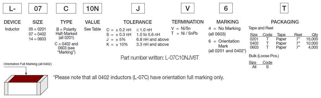
How to Order