C-Series, NPO, Low ESR Capacitor Multi-Layer High-Q Capacitors (New Product Release)
Available in PDF
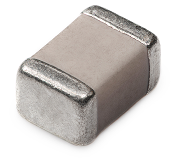
Johanson is proud to announce the new C-Series High Frequency Multilayer Ceramic Capacitors. These ultra-low loss capacitors are made with Copper electrodes, instead of Palladium and Silver, making them less subject to the price volatility of precious metals. Therefore, prices for these low ESR capacitors will be more stable over time. Available in three cases sizes (0402, 0603, 0805), this series features an enhanced ESR of over 1.5GHz, and was developed with two key design criteria - reliability and lot-to-lot RF consistency. Applications include low power RF, smart metering, RF remote control, broadband wireless equipment, cellular base station equipment, RF matching and filter networks and RF microwave test equipment.
Key Features:
- EIA case sizes from 0402, 0603 and 0805
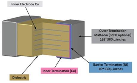
- Lead Free Terminations:
- Electrodes: Cu
- Core Termination: Cu
- Barrier Layer: Ni
- External Termination Layer: 100% Sn Standard
- Enhanced High-Q / Low Loss NPO – Lower Loss than Standard NPO
- RoHS Compliant w/ standard 100% Tin termination
- Stable COG (NPO) temperature coefficient
- Highly reliable performance
- Industry standard case sizes
- Lower Price than Pd/Ag products
- Enhanced ESR over 1.5 GHz
- Temperature range is -55° C to +150° C*.
*On request, we can extend the highest temperature to +150° C for any of our high-Q series
Applications:
- Cellular Phone
- Low Power RF
- Handheld Computers & Tablets
- RF Remote Control
- Smart Metering
- Cellular Base Station Equipment
- Broadband Wireless Equipment
- RF Matching & Filter Networks
- Decoupling, Bypass, & DC Block
- Broadband Wireless Equipment
- RF and Microwave Test Equipment
- Wireless LAN Equipment
Advantages of a Low Loss Capacitor
- Extended battery life in mobile equipment
- Increased power output and higher efficiency from RF power amplifiers
- Reduced amount of heat generated through ultra-low ESR and High-Q
- The signal to noise ratio and overall noise temperature can be improved
- Lower in-band insertion loss (S21) when used in filter networks
C-Series Capacitors Information
Model Selection
| EIA Size/Cap. Value | RF Power Applications | ||||
|---|---|---|---|---|---|
| NEW | NEW | NEW | |||
| 0402 (QCCF) | 0603 (QCCP) | 0805 (QCCT) | |||
| pF | Code | Voltage | Voltage | Voltage | |
| 0.1 | 0R1 | 250V | 500V | 1000V | |
| 0.2 | 0R2 | 250V | 500V | 1000V | |
| 0.3 | 0R3 | 250V | 500V | 1000V | |
| 0.4 | 0R4 | 250V | 500V | 1000V | |
| 0.5 | 0R5 | 250V | 500V | 1000V | |
| 0.6 | 0R6 | 250V | 500V | 1000V | |
| 0.7 | 0R7 | 250V | 500V | 1000V | |
| 0.8 | 0R8 | 250V | 500V | 1000V | |
| 0.9 | 0R9 | 250V | 500V | 1000V | |
| 1.0 | 1R0 | 250V | 500V | 1000V | |
| 1.1 | 1R1 | 250V | 500V | 1000V | |
| 1.2 | 1R2 | 250V | 500V | 1000V | |
| 1.3 | 1R3 | 250V | 500V | 1000V | |
| 1.4 | 1R4 | 250V | 500V | 1000V | |
| 1.5 | 1R5 | 250V | 500V | 1000V | |
| 1.6 | 1R6 | 250V | 500V | 1000V | |
| 1.7 | 1R7 | 250V | 500V | 1000V | |
| 1.8 | 1R8 | 250V | 500V | 1000V | |
| 1.9 | 1R9 | 250V | 500V | 1000V | |
| 2.0 | 2R0 | 250V | 500V | 1000V | |
| 2.1 | 2R1 | 250V | 500V | 1000V | |
| 2.2 | 2R2 | 250V | 500V | 1000V | |
| 2.4 | 2R4 | 250V | 500V | 1000V | |
| 2.7 | 2R7 | 250V | 500V | 1000V | |
| 3.0 | 3R0 | 250V | 500V | 1000V | |
| 3.3 | 3R3 | 250V | 500V | 1000V | |
| 3.6 | 3R6 | 250V | 500V | 1000V | |
| 3.9 | 3R9 | 250V | 500V | 1000V | |
| 4.3 | 4R3 | 250V | 500V | 1000V | |
| 4.7 | 4R7 | 250V | 500V | 1000V | |
| 5.1 | 5R1 | 250V | 500V | 1000V | |
| 5.6 | 5R6 | 250V | 500V | 1000V | |
| 6.2 | 6R2 | 250V | 500V | 1000V | |
| 6.8 | 6R8 | 250V | 500V | 1000V | |
| 7.5 | 7R5 | 250V | 500V | 1000V | |
| 8.2 | 8R2 | 250V | 500V | 1000V | |
| 9.1 | 9R1 | 250V | 500V | 1000V | |
| 10 | 100 | 250V | 500V | 1000V | |
| 11 | 110 | 250V | 500V | 1000V | |
| 12 | 120 | 250V | 500V | 1000V | |
| 13 | 130 | 250V | 500V | 1000V | |
| 15 | 150 | 250V | 500V | 1000V | |
| 16 | 160 | 250V | 500V | 1000V | |
| 18 | 180 | 250V | 500V | 1000V | |
| 20 | 200 | 250V | 500V | 1000V | |
| 22 | 220 | 250V | 500V | 1000V | |
| 24 | 240 | 250V | 500V | 1000V | |
| 27 | 270 | 250V | 500V | 1000V | |
| 30 | 300 | 250V | 500V | 1000V | |
| 33 | 330 | 250V | 500V | 1000V | |
| 36 | 360 | 500V | 1000V | ||
| 39 | 390 | 500V | 1000V | ||
| 43 | 430 | 500V | 1000V | ||
| 47 | 470 | 500V | 1000V | ||
| 51 | 510 | 500V | 1000V | ||
| 56 | 560 | 500V | 1000V | ||
| 62 | 620 | 500V | 1000V | ||
| 68 | 680 | 500V | 1000V | ||
| 75 | 750 | 500V | 1000V | ||
| 82 | 820 | 500V | 1000V | ||
| 91 | 910 | 500V | 1000V | ||
| 100 | 101 | 500V | 1000V | ||
| 110 | 111 | 500V | |||
| 120 | 121 | 500V | |||
| 130 | 131 | 500V | |||
| 150 | 151 | 500V | |||
| 160 | 161 | 500V | |||
| 180 | 181 | 500V | |||
| 200 | 201 | 500V | |||
| 220 | 221 | 500V | |||
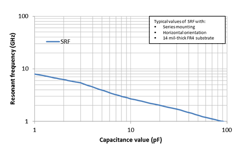
Resonant frequencies
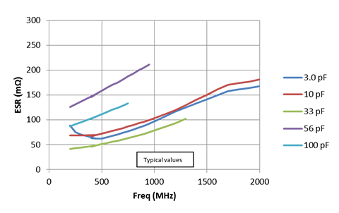
ESR curves
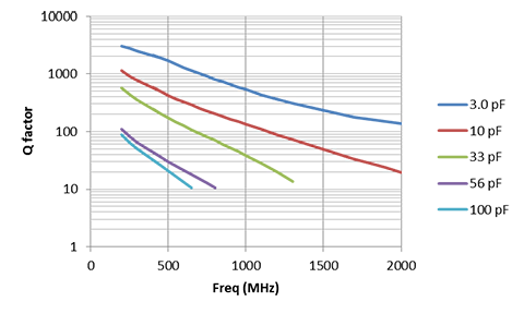
Q factor curves
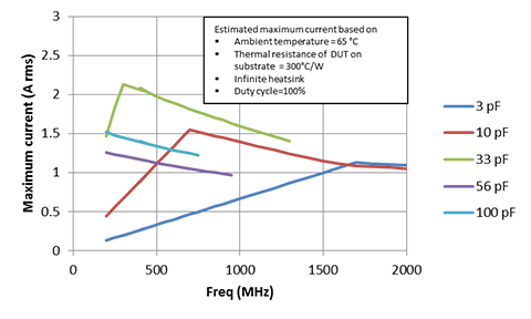
Maximum RF Current (estimated)
Mechanical Characteristics
| Size | Units | Length | Width | Thickness | End Band |
|---|---|---|---|---|---|
| 0402 | in | .040 ± .004 | .020 ± .004 | .020 ± .004 | .010 ± .006 |
| 0603 | in | .062 ± .006 | .032 ± .006 | .03 ± .005/-.003 | .014 ± .006 |
| 0805 | in | .080 ± .008 | .050 ± .008 | .040 ± .006 | .020 ± .010 |
Environmental Specifications
| Specification | Test Parameters | |
| Life test: | No mechanical damage. Capacitance change: ±3.0% or 0.3 pF Q>500 I.R. >1 G Ohms Breakdown voltage: 2.5 x WVDC | Applied voltage: 200% rated voltage, 50 mA max. Temperature: 150°±3°C Test time: 1000+48-0 hours |
| Thermal Cycle: | No mechanical damage. Capacitance change: ±2.5% or 0.25pF Q>2000 I.R. >10 G Ohms | 5 cycles of: 30±3 minutes @ -55°+0/-3°C, 2-3 min. @ 25°C, 30±3 min. @ +150°+3/-0°C, 2-3 min. @ 25°C Measure after 24±2 hour cooling period |
| Humidity, Steady State: | No mechanical damage. Capacitance change: ±5.0% or 0.50pF max. Q>300 I.R. = 1 G-Ohmbr /> Breakdown voltage: 2.5 x WVDC | Relative humidity: 90-95% Temperature: 40°±2°C Test time: 500 +12/-0 Hours Measure after 24±2 hour cooling period |
| Humidity, Low Voltage: | No mechanical damage. Capacitance change: ±5.0% or 0.50pF max. Q>300 I.R. = 1 G-Ohm min. Breakdown voltage: 2.5 x WVDC | Applied voltage: 1.5 VDC, 50 mA max. Relative humidity: 85±2% Temperature: 40°±2°C Test time: 240 +12/-0 Hours Measure after 24±2 hour cooling period |
| Vibration: | No mechanical damage. Capacitance change: ±2.5% or 0.25pF Q>1000 I.R. = 10 G-Ohm Breakdown voltage: 2.5 x WVDC | Cycle performed for 2 hours in each of three perpendicular directions. Frequency range 10Hz to 55 Hz to 10 Hz traversed in 1 minute. Harmonic motion amplitude: 1.5mm. |
Automotive applications (AEC-Q200): additional requirements – please consult factory for details.
How to Order
Valid options are shown except for Capacitance
A typical PN is QCCP5001Q100J1GV001T. This part number breaks down as follows:
High-Q MLC C-Series, 0402, Hi-Q NP0/C0G, 25V, 10pF±1%, Ni/Au (RoHS), Bulk