APPLICATION NOTES
S-Parameter Measurements
Introduction:
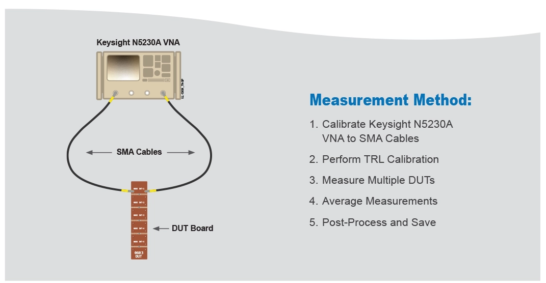
Johanson Technology offers downloadable S-Parameter libraries for our RF Capacitors, EMI Filters, and Inductors. These are available in series-through or shunt-through configuration for all sizes. Series-thru configurations are typical for power transfer or DC block circuits where shunt-thru are mostly bypass or filtering networks. Positioning the capacitor in either of these configurations is shown to have different RF behavior. Johanson has made every effort to ensure that our data is accurate, replicable, and comparable to today’s industry-standard. The published data is intended to make it easier for designers, students, and engineers to model the component behavior as would be measured on the first prototype. It is necessary to include calibration when measuring S-Parameters for various reasons: To avoid measurement errors, to separate effects of the transmission medium from the Device Under Test (DUT), and to account for imperfections that cause non-ideal results. Johanson uses a pre-measurement correction system Thru-Reflect-Line (TRL) and a Grounded Coplanar Waveguide (GCPW) with via stitching as the transmission medium. The overall measurement is made on the Keysight N5230A Vector Network Analyzer from 300KHz – 20GHz. The following text will outline the overall measurement method used for S-Parameters as well as a brief overview of its operation.
Structure:
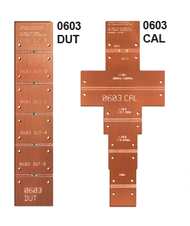
TRL calibration is a pre-measurement error correction method used to provide high accuracy measurements of our DUTs. Through various 2-port measurements, a full 12-term error model can be determined for VNA calibration. By applying a through, open (reflect), load and transmission lines with a known characteristic impedance, a broadband calibration kit is developed. Johanson uses a high-performance dielectric for fabrication consistency and to calculate time of flight delays within the medium.
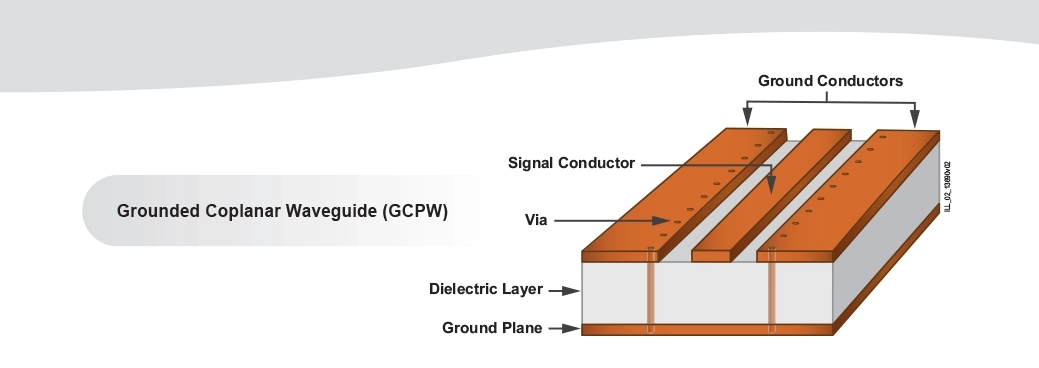
A grounded coplanar waveguide is a signal conductor between two ground conductors above a dielectric layer, with an additional ground layer below the dielectric. By utilizing a copper pour and ground plane, the design provides additional shielding along the trace and more isolation compared to microstrip. The impedance of the GCPW is primarily controlled by the gap between the conducting trace and coplanar grounds, which is designed to be 50 Ohms. GCPW was chosen over microstrip due to the lower radiation loss and dispersion at higher frequencies. Plated through via holes are used to connect the top and bottom ground planes while behaving as a “microwave wall” within the waveguide. Johanson Technology uses via stitching or a “via fence” to improve bandwidth of the GCPW.
Tapering is used to help match the width of the conducting trace to the SMA launch pins. Typically, the pins from the SMA launch add additional capacitance to the measurements, however, by tapering or narrowing the trace, inductance is added to the board. Tapering is used to optimize performance and improve the overall match. Metal backers are also used for thin board (~0.010” thick) support when connecting RF cables.
Plated through via holes are used to connect the top and bottom ground planes while behaving as a “microwave wall” within the waveguide. Johanson Technology uses via stitching or a “via fence” to improve bandwidth of the GCPW Tapering is used to help match the width of the conducting trace to the SMA launch pins. Typically, the pins from the SMA launch add additional capacitance to the measurements, however, by tapering or narrowing the trace, inductance is added to the board. Tapering is used to optimize performance and improve the overall match. Metal backers are also used for thin board (~0.010” thick) support when connecting RF cables.
References:
Agilent Stripline TRL Calibration Fixtures for 10-Gigabit Interconnect Analysis White Paper, Agilent Technologies, 5 Apr. 2006, https://silo.tips/ download/agilent-stripline-trl-calibration-fixtures- for-10-gigabit-interconnect-analysis.
Optimizing Test Boards for 50 GHz End Launch Connectors. Southwest Microwave, https://www.hasco-inc.com/technical- articles/southwest-microwave-connectors/ optimizing-test-boards-for-end-launch-connectors
Comparing PCBs for Microstrip and Grounded Coplanar Waveguide Circuits. Rogers Corporation, 4 Aug. 2020, https://rogerscorp.com/ blog/2020/comparing-pcbs-for-microstrip-and- grounded-coplanar-waveguide-circuits.
Sain, Arghya. “Impact of Ground via Placement in Grounded Coplanar Waveguide Interconnects.” Impact of Ground Via Placement in Grounded Coplanar Waveguide (GCPW) Interconnects, IEEE, Jan. 2016, https://ieeexplore.ieee.org/ document/7365442.
S-Parameter specification, “Touchstone® File Format Specification Rev 2.0”, EIA/IBIS Open Forum 2009, https://ibis.org/touchstone_ver2.0/ touchstone_ver2_0.pdf